Contents
- The Eleven Bending Methods at a Glance
- Group One: V-Bending, Air Bending, Bottoming and Coining
- Group Two: Seven Dedicated Bending Methods
- Chapter Three: The Factors That Really Decide the Outcome
- Chapter Four: Choosing a Method for Your Part
- Chapter Five: Design Checks Before Releasing a Bending Drawing
- Chapter Six: Which Machine Goes with Which Method
- Frequently Asked Questions
The most expensive sentence in a fabrication shop is we have always done it this way. It may well be right, but it may also mean that a batch of parts is being formed with the wrong method, with angles rescued by manual compensation, and a set of judgement criteria that were never written down. This guide does something different: it covers the full range of bending methods in one place, so that the moment a drawing lands on your desk you can say which method this part needs and why.
More importantly, these methods are not alternatives competing with each other; they divide the work. Air bending is flexible but springs back, bottoming is consistent but needs different tooling for every angle, and coining is the most accurate but only for thin sheet. The dedicated methods such as hemming, offset bending and U bending should not be improvised with an ordinary V die at all. The cost of choosing wrongly is not only an angle error: it can be tooling worn out early, a whole batch scrapped, or marks on a cosmetic part that will not come off.
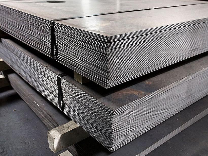
The photograph below is the most common starting point in a bending shop: a stack of steel waiting to be worked. What follows is how that flat blank becomes the shape on your drawing. We begin with the basic forming methods performed on a press brake, work through seven dedicated methods, and then answer three questions: which factors really drive the outcome, how to choose for a given part, and what to check on a drawing before releasing it.
1. The Eleven Bending Methods at a Glance
The table below lists the types most commonly encountered in press-brake and fabrication work. They can be grouped by forming method, tooling configuration or resulting bend geometry, but for practical purposes it helps to know all of them by name.
A few clarifications are worth making up front, because they determine how the rest of this guide reads.
- V-bending describes a tooling configuration: a V-shaped punch pressing sheet metal into a V-die. It is a broad category that includes air bending, bottoming and coining as forming methods. These three differ significantly in how far the punch descends and how much force is applied.
- U-bending, offset bending and hemming describe the geometry or operation being performed. Any of them may involve multiple press-brake strokes or dedicated tooling.
- One terminology note: coining here refers to the press-brake forming mode, not the stamping process used to produce coins. The compressive working principle is similar, but the application is angular sheet-metal bending.
| Type | What it produces | Typical application |
|---|---|---|
| V-Bending | Angular bends using a V-punch and V-die | Brackets, panels, general fabrication |
| Air Bending | Variable-angle bends; stroke-controlled | High-mix production, prototyping |
| Bottoming | Consistent angular bends; die-conforming | Repetitive production runs |
| Coining | Precise angular bends; low springback | Thin precision sheet, tight tolerances |
| U-Bending | U-shaped channels and profiles | Structural channels, enclosures |
| Wipe Bending | Short edge flanges | Cabinets, HVAC ductwork, enclosures |
| Roll Bending | Large-radius arcs, cylinders, cones | Tanks, curved panels, pipe sections |
| Rotary Bending | Angular bends with minimal surface marking | Pre-painted or polished sheet |
| Folding | Long panel edges; no tooling marks on face | Architectural panels, large enclosures |
| Offset Bending | Stepped Z-shaped profiles | Brackets, mounting plates, HVAC |
| Hemming | Folded-back double-thickness edges | Appliance panels, enclosure lids, duct seams |
2. Group One: V-Bending, Air Bending, Bottoming and Coining
These four are different ways of using the same tooling configuration, and they cover most of the bending work any shop actually runs.
2.1 1.1 V-Bending
V-bending covers any angular bend formed with a V-punch and V-die on a press brake. The punch descends into the die opening, bending the sheet at the point of contact. Depending on how the process is controlled, that is stroke depth, applied force and die geometry, the same V-die setup can be used for air bending, bottoming or coining.
The V-die opening is one of the most important parameters. A wider opening reduces the required bending force and produces a larger inside radius; a narrower opening increases force and tightens the radius. V-die width is typically selected based on material thickness, following guidelines from the tooling manufacturer.
V-bending is the starting point for most press-brake work. Angular brackets, panel flanges, channel sections and box enclosures are all built on V-bends. The choice of forming method, whether air, bottoming or coining, determines the precision and repeatability that can be achieved. For a worked reference on how die opening relates to material thickness, the GWMT guide on V-die opening covers the ratio table with worked examples.
- Typical applications: structural brackets, mounting plates, enclosure panels, HVAC components, sheet metal boxes
2.2 1.2 Air Bending
Air bending is the most common press-brake method in general fabrication. The punch drives the sheet partway into the V-die opening; the sheet contacts only the punch tip and the two die shoulders, and the die bottom is never touched. The bend angle is controlled by stroke depth rather than by die angle, so one punch-and-die combination can produce a range of angles by adjusting how far the ram descends.
This flexibility is the main reason air bending dominates mixed-batch shops. You can form 90 degree brackets, then readjust the stroke for 120 degree gussets on the same tooling without a change. For prototypes or short runs with varied geometry, this matters.
The trade-off is springback. When the punch retracts, the metal recovers elastically toward its original shape, and how much recovery occurs depends on material grade, temper, thickness and grain orientation. CNC press brakes with back-gauge correction and real-time angle measurement handle this effectively, but springback must always be accounted for. It cannot be ignored. Required tonnage is lower than for bottoming or coining, which makes air bending accessible on smaller machines and practical on thicker material where the force needed for coining would be impractical.
- Best suited for: high-mix production, prototyping, varied angles from a single setup, and operations where flexible tooling use matters more than maximum precision
2.3 1.3 Bottoming
In bottoming the sheet is pressed firmly into the V-die so that it closely conforms to the die angle. Unlike coining the material is not intentionally penetrated and heavily compressed by the punch tip, but the degree of contact is significantly greater than in air bending. This closer die conformance reduces the degree of elastic recovery and makes the bend angle more consistent from part to part.
The key practical difference from air bending: the punch angle and die angle must closely match the target bend angle, and the V-die opening must suit both material thickness and required inside radius. Switching to a different angle typically requires a tooling change, which increases setup time per angle but delivers better repeatability once locked in.
A common misconception is that bottoming eliminates springback. It reduces it noticeably compared with air bending, but some recovery still occurs depending on the material. Bottoming sits between air bending and coining in terms of force, flexibility and precision.
- Best suited for: medium-to-high production runs where consistent angle repeatability is critical and air bending springback variability is unacceptable
2.4 1.4 Coining
Coining applies substantially higher press force, enough to exceed the material yield strength across the entire bend zone. The punch tip penetrates the material, locally thinning it at the bend line and permanently setting the angle. Because the deformation is predominantly plastic, springback is minimal.
The practical costs are real. Required tonnage is considerably higher than bottoming or air bending, and tooling wear is accelerated. Coining is generally more economical on thin sheet than heavy plate, because coining thick material demands force levels that exceed most production press-brake capacities. Coining can be useful for thin-sheet applications where very consistent bend angles are required, including some precision components used in aerospace, electronics and medical equipment.
- Best suited for: thin sheet, high-precision parts with tight angular tolerances, and applications where springback compensation through CNC stroke control is insufficient
3. Group Two: Seven Dedicated Bending Methods
Not every part geometry is suited to a press brake with a V-die. U-shaped profiles, long panel edges, continuous curves, edge flanges and folded edges each have a forming method better matched to the task.
3.1 2.1 U-Bending and Channel Bending
U-bending forms a U-shaped profile, two parallel flanges with a flat base, in a single operation using a U-shaped punch and matching die. The result is a clean channel cross-section without the positioning errors that can accumulate when forming U-channels with two separate V-bending operations.
The geometry constraint is significant: the punch must physically fit inside the formed channel. As channel depth increases, standard punch heights may become insufficient, and the required inside radius of the base is determined by the punch nose radius. For wide, shallow channels a standard U-die is often practical; for narrow or deep channels dedicated tooling is necessary.
In lower-volume or prototype situations, U-channels are commonly formed with two sequential V-bending operations. The bend sequence must be planned carefully so that the second bend does not cause the first flange to collide with the tooling.
- Typical applications: structural channels, cable management sections, enclosure frames, HVAC support sections
3.2 2.2 Folding
Folding uses a clamping beam to hold the sheet flat against a bed, then swings a folding beam upward or downward to form the bend. The sheet stays stationary throughout. Because no punch presses against the sheet surface into a die cavity, the visible face typically shows no tooling contact marks, an important advantage for pre-painted sheet, coated materials and architecturally visible panels.
Folding also handles long panel edges and wide sheet blanks more easily than a press brake, where a large workpiece must be manually repositioned against a back-gauge. The constraint is part geometry: the blank and any previously formed flanges must clear the folding beam through the full stroke. Parts with multiple closely spaced bends or complex profiles may not be compatible with a standard folding machine geometry.
- Typical applications: architectural cladding panels, enclosure lids, large electrical cabinet skins, pre-painted or coated sheet products
3.3 2.3 Wipe Bending
Wipe bending, also called edge bending, clamps the sheet against a pressure pad, leaving a projecting flange that a punch sweeps over a die edge to form the bend. The process is fast and produces consistent flange angles, common in enclosure fabrication, HVAC ductwork and electrical cabinet manufacturing where short, uniform flanges are needed in volume.
The inner radius of the bend is limited by the punch nose and die edge geometry. Because the punch wipes across the sheet surface, marks or scratches on the inner face are possible, particularly on coated or polished materials. This makes wipe bending a poor choice for cosmetically critical inner surfaces, but a practical one for structural or hidden flanges.
- Typical applications: short edge flanges on enclosures, HVAC duct connections, cabinet panels, electrical housing components
3.4 2.4 Roll Bending
Roll bending uses a set of powered rolls, typically three, to progressively bend sheet or plate into an arc, cylinder or cone. The sheet passes through the rolls repeatedly, and the position of the adjustable roll determines the radius of curvature. There are no sharp angular bends; the output is a smooth, continuous curve.
The process is the standard choice for cylindrical tank shells, pressure vessel sections, curved architectural panels, pipe sections fabricated from plate, and structural curved elements. Sheet width and plate thickness are the primary machine-capacity constraints. One point to plan for: the leading and trailing edges of the sheet pass through the rolls with less forming action than the middle section, leaving short end flats at both ends. If the design requires a full arc to the edge, those end flats need to be pre-bent on a press brake first, or trimmed after rolling.
For the full principle of roll position, pre-bending and springback in plate rolling, the GWMT guide on how a plate rolling machine forms a shell covers it in detail.
- Typical applications: cylindrical tank shells, pressure vessel sections, curved architectural panels, pipe sections, structural curved elements
3.5 2.5 Rotary Bending
Rotary bending uses a rotating forming die that rolls against the sheet rather than sliding a punch across it. Because the contact is rolling rather than dragging, surface friction is reduced and tooling marks are minimised, relevant for pre-painted, anodised or polished materials where a standard press-brake punch would leave visible marks.
Rotary tooling can also form bends slightly past 90 degrees in a single stroke, which is useful for overbending springy alloys where extra angle is needed to compensate for springback. It is a press-brake tooling type, not a separate class of machine. It should not be confused with rotary draw tube bending, which uses an internal mandrel to prevent a tube from collapsing during bending, a different process used for pipes and structural sections rather than flat sheet.
- Typical applications: pre-painted sheet components, appliance panels, decorative sheet metal, and applications requiring bends beyond 90 degrees without tooling marks
3.6 2.6 Hemming
Hemming folds the edge of a sheet back on itself, creating a double-thickness edge that is safer to handle, stiffer and more resistant to distortion than a raw sheared edge. It is a two-step operation: first an acute pre-bend, typically 30 to 45 degrees, using an acute-angle punch, then a flattening stroke using a hem die or the press-brake bed to close the fold.
Two hem types are common. An open hem is not fully closed: a controlled gap or radius remains, which reduces stress on the material and is useful for creating seam joints between two panels. A closed hem is pressed flat, with the folded leg fully against the parent sheet. A hem is distinct from a simple flange: a flange projects away from the sheet at an angle, while the hem leg folds back toward the sheet. Specifying the correct type prevents tooling confusion during setup.
Before hemming, check three things.
- Material ductility: hard-temper aluminium, work-hardened stainless and high-carbon steel all carry cracking risk at the hem radius, so use softer temper material or anneal where feasible
- Minimum flange length: the pre-bent leg must be long enough to reach the die flat during the closing stroke, and the tooling datasheet defines the practical minimum based on sheet thickness
- Grain direction: on many alloys, hemming parallel to the rolling direction increases cracking risk compared with hemming perpendicular to it
- Typical applications: appliance panel edges, HVAC duct seams, enclosure lids, architectural sheet edges
3.7 2.7 Offset Bending
Offset bending, also called jog bending or Z-bending, produces a stepped cross-section: two parallel planes offset from each other, connected by a short angled web. The resulting Z-shaped profile is used wherever one face of a part must be positioned at a different height than another for assembly fit or clearance.
A dedicated offset die can form both bends simultaneously in a single press stroke when the step height and step width fall within the die range. For steps outside that range, or on long parts where single-stroke forming would require excessive force, two separate press-brake hits are used with careful back-gauge repositioning between them. Closely spaced offsets on a single part require careful bend-sequence planning: the first bend changes the part reference geometry, which affects back-gauge positioning and tooling clearance for the second.
- Typical applications: structural mounting brackets, HVAC duct connections, control panel faces, equipment enclosures requiring stepped faces
4. Chapter Three: The Factors That Really Decide the Outcome
The process choice is only part of the equation. Several technical factors determine whether a bend will actually hit its drawing dimensions consistently in production.
- Material and thickness: different alloys and tempers behave differently under bending load. Harder materials require more force and exhibit more springback, while thicker sheet demands larger V-die openings and higher press tonnage. Confirming material grade and thickness before process selection is not optional.
- Inside bend radius: it affects tooling selection, springback magnitude and whether the material will crack. A radius smaller than the material thickness places high tensile stress on the outer fibre. Minimum bend radius values vary by alloy and temper, and the material supplier or tooling manufacturer reference tables are the reliable source.
- Springback: all elastic-plastic materials spring back partially after the punch retracts. The degree depends on material, thickness, temper, bend radius and forming method. Air bending produces the most springback, bottoming reduces it and coining minimises it. CNC press brakes manage springback through programmed overbend compensation or real-time angle feedback.
- K-factor and bend allowance: the K-factor is a ratio describing where the neutral axis sits within the sheet thickness during bending, the layer of material that neither stretches nor compresses. It affects the bend allowance, the length of material consumed at the bend. Accurate bend allowance calculation is necessary to correctly size the flat blank, and K-factor values vary by material, thickness, inside radius and forming method. An incorrect value results in parts that are consistently too long or too short.
- V-die opening: the width determines the required bending force, the minimum achievable inside radius and the degree of springback in air bending. Too narrow and force increases sharply; too wide and the bend radius grows and accuracy suffers. V-die width is typically selected as a multiple of material thickness, following the tooling manufacturer guidelines.
- Bend force and machine capacity: estimated bending force must stay within the press brake rated capacity for the bend length in question. Bottoming and coining demand significantly more tonnage than air bending for the same material and thickness. Exceeding machine capacity causes deflection, inaccuracy and potential equipment damage.
5. Chapter Four: Choosing a Method for Your Part
The decision starts with the required geometry, then narrows through material, tolerance, surface finish, batch size and available equipment.
- Geometry first: continuous curve leads to roll bending, long panel edge to folding, short edge flange in volume production to wipe bending, and angular flanges on a press brake to a choice between air bending, bottoming or coining based on the following factors.
- Material type and thickness: harder alloys and heavier gauges require more force and exhibit more springback. High-strength stainless steel and spring-temper aluminium steer toward bottoming for consistent results, while softer low-carbon steel in thin gauges is forgiving with air bending.
- Inside bend radius: verify the minimum bend radius for the specific alloy and temper before finalising the drawing. This also drives V-die opening selection.
- Required angle tolerance: standard press-brake operations under controlled conditions can typically achieve around plus or minus one degree. Tighter tolerances may require better tooling, bottoming, real-time angle measurement or coining. Actual capability varies by machine, material, thickness and tooling condition.
- Surface appearance: pre-painted, anodised or polished sheet calls for folding or rotary tooling to minimise marking. Raw structural steel with no cosmetic requirement takes standard air bending or bottoming.
- Batch size and changeover: air bending minimises tooling changes across varied angles, since one setup handles many angles by adjusting stroke. Bottoming and coining need angle-matched tooling, which increases changeover time on mixed-angle jobs.
- Machine capacity: confirm that the tonnage required for bottoming or coining is within the machine rated capacity for the bend length and material.
| Part scenario | Recommended starting point |
|---|---|
| Mixed-batch brackets, varied angles, moderate tolerance | Air bending, single setup with stroke adjusted per angle |
| High-volume edge flanges, consistent angle | Wipe bending or bottoming, fast and repeatable once set |
| Large-radius curved shell, tank or curved architectural panel | Roll bending, purpose-built for continuous curves |
| Long cosmetic panel in pre-painted or coated sheet | Folding, minimises tooling contact on the visible face |
| Thin precision parts with tight angular tolerance | Coining, if tonnage is available and throughput justifies tooling wear |
| U-shaped structural channel | U-bending die, or two-hit V-bending with sequence planning |
6. Chapter Five: Design Checks Before Releasing a Bending Drawing
Most fabrication problems traced to bending have their root in the drawing. Running through these checks before releasing the part avoids predictable issues.
- On the drawing: specify material grade, temper and nominal thickness explicitly, because steel sheet on its own is not sufficient.
- Call out the inside bend radius, not just the angle, because the inside radius determines V-die selection and drives bend allowance calculations.
- Set realistic tolerances. As a practical reference many standard press-brake setups can achieve around plus or minus one degree under controlled conditions, and tighter tolerances require better equipment, tooling or process, so confirm capability with the fabricator before committing.
- Keep holes and slots away from the bend zone. A common starting rule is to position holes at a distance based on both material thickness and inside bend radius, a formula such as two times T plus R is widely used as a reference, but the actual minimum depends on hole size, material and tooling. When in doubt, ask the fabricator.
- Draw the bend sequence and confirm that the punch can physically enter any channel or box that earlier bends have created.
- For hems, confirm the pre-bend flange length is sufficient for the closing stroke, and check material ductility for cracking risk.
- For offset bends, verify that step height and step width fall within the available die range, or plan for two separate hits.
- For roll-bent parts, identify the end flats and decide whether they need a press-brake pre-bend or are acceptable in the finished part.
- Surface requirements: flag cosmetically critical faces to the fabricator, who can adjust tooling material, die coatings and press speed accordingly. If the part is powder-coated or painted after forming, minor tool marks are usually acceptable; pre-finished sheet is unforgiving and process selection must account for this from the start.
7. Chapter Six: Which Machine Goes with Which Method
The bending method determines the equipment required. This is directly relevant when specifying a process, quoting a job or evaluating whether a particular shop can produce a part.
A CNC press brake is the most versatile machine on this list: it covers air bending, bottoming, coining, U-bending, wipe bending, rotary bending, offset bending and hemming through tooling changes. Folding machines and plate rolls are separate equipment for their respective operations.
For shops evaluating CNC press brake options, the starting point is to establish which forming methods the machine will be expected to handle and at what tonnage. The GWMT press brake guide covers types, working principle, tonnage calculation and selection in turn, while the press brake buying guide provides a fifteen-step checklist from requirement to acceptance.
| Bending type | Typical equipment |
|---|---|
| Air bending | CNC press brake |
| Bottoming | CNC press brake |
| Coining | High-tonnage CNC press brake |
| V-bending (general) | Press brake |
| U-bending | Press brake with U-die, or dedicated U-bending tooling |
| Wipe bending | Press brake with wipe tooling, or dedicated wipe bending machine |
| Folding | Panel folding machine / folder-bender |
| Roll bending | Plate rolling machine (3-roll or 4-roll) |
| Rotary bending | Press brake with rotary tooling |
| Offset bending | Press brake with offset (joggle) die |
| Hemming | Press brake with acute punch and hem die |
8. Frequently Asked Questions
The seven questions below suit item-by-item confirmation with a customer, a colleague or a supplier.
- What are the main types of sheet metal bending?
The main types include V-bending, air bending, bottoming, coining, U-bending, wipe bending, roll bending, rotary bending, folding, offset bending and hemming. Some describe how the sheet is formed, namely air bending, bottoming and coining; others describe the resulting geometry or operation, namely U-bending, hemming and offset bending. V-bending is a broad tooling configuration that includes air bending, bottoming and coining as forming methods.
- What is the difference between air bending and bottoming?
Both use a V-punch and V-die on a press brake. In air bending the punch stops before the sheet contacts the die bottom: the bend angle is set by stroke depth and one tool set handles multiple angles. In bottoming the sheet is pressed more firmly into the V-die until it closely conforms to the die angle. Bottoming generally reduces springback variability and improves repeatability, but it requires more force and matched tooling for each angle.
- Is coining suitable for thick plate?
Generally no. Coining requires sufficient force to plastically compress the material at the bend zone, which scales with material thickness. For thick plate the required tonnage quickly exceeds practical press-brake capacity, and coining is most economical on thin sheet. For thick material with tight angle tolerances, bottoming on a well-calibrated machine is the more practical approach.
- What causes springback in sheet metal bending, and how is it managed?
Springback occurs because bending stresses the material beyond its yield point on the outer fibre while the inner zone remains partially elastic. When the punch retracts, the elastic zone recovers and opens the bend angle slightly. It is managed by overbending, programming extra angle as compensation, by selecting bottoming or coining to reduce the elastic recovery zone, or by using closed-loop angle measurement systems on the press brake.
- What is K-factor in sheet metal bending?
The K-factor is a ratio that defines where the neutral axis sits within the sheet thickness during bending, specifically the distance from the inner face to the neutral axis divided by the sheet thickness. It determines how much material is consumed by the bend, the bend allowance. K-factor values vary by material, temper, inside radius and forming method. Using the correct K-factor is necessary to accurately size the flat blank before bending.
- When should a folding machine be used instead of a press brake?
Folding suits large panels that are awkward to handle on a press brake, and parts made from pre-finished or surface-sensitive sheet where tooling marks on the visible face are unacceptable. A press brake is more versatile for multi-bend parts and higher-force operations. The constraint on folding machines is geometry: the blank and all previously formed flanges must clear the folding beam throughout the stroke.
- What is a hem, and how is it different from a flange?
A hem folds the sheet edge back on itself: the folded portion lies against or close to the parent sheet, creating a double-thickness edge. A flange, by contrast, projects away from the sheet at an angle. In other words, a hem folds toward the sheet and a flange folds away from it. That distinction changes both the tooling and the forming operation, which is why specifying the correct type matters.
Technical references
Manufacturer references support process explanations; images illustrate selection topics, not an approved GWMT supply specification.