Product inquiries
All solutions

SOLUTION 06 · BENDING ENHANCEMENT

Press brake backgauge system

Position each bend around the workpiece. Review travel, fingers, controlled movements and repeatability as one coordinated machine system.

Explore positioning options

POSITIONING SYSTEM

Accurate positioning starts at the part datum.

The backgauge helps locate the sheet for each bend. Its useful configuration depends on flange dimensions, bend sequence, material handling and the selected press brake—not an axis count in isolation.

Datum and finger contact Travel and clearance Controlled movement
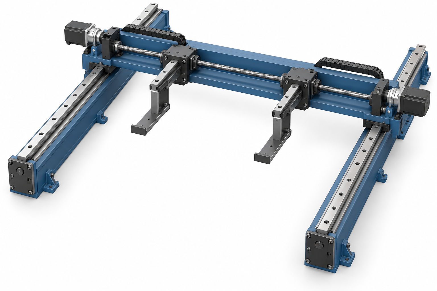
Concept illustration of rear-gauge rails, crossbeam, drives and two fingers
Conceptual assembly illustration; actual equipment arrangement to be confirmed.

CONFIGURATION REVIEW

Choose movement by function, not by the headline number.

These examples organize a technical discussion. They are not standard packages or confirmed capabilities for every press brake.

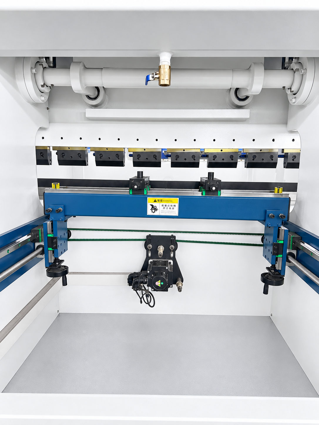
Press brake rear-gauge fingers and guide railsComponent reference · final arrangement to be confirmed
01 POSITIONING PATH

2-axis positioning

X + R review

A starting point for repeatable depth setting and gauge-finger height adjustment on regular bending work.

  • Confirm minimum and maximum flange depth
  • Check finger height, clearance and part support
  • Match travel and feedback to the selected machine
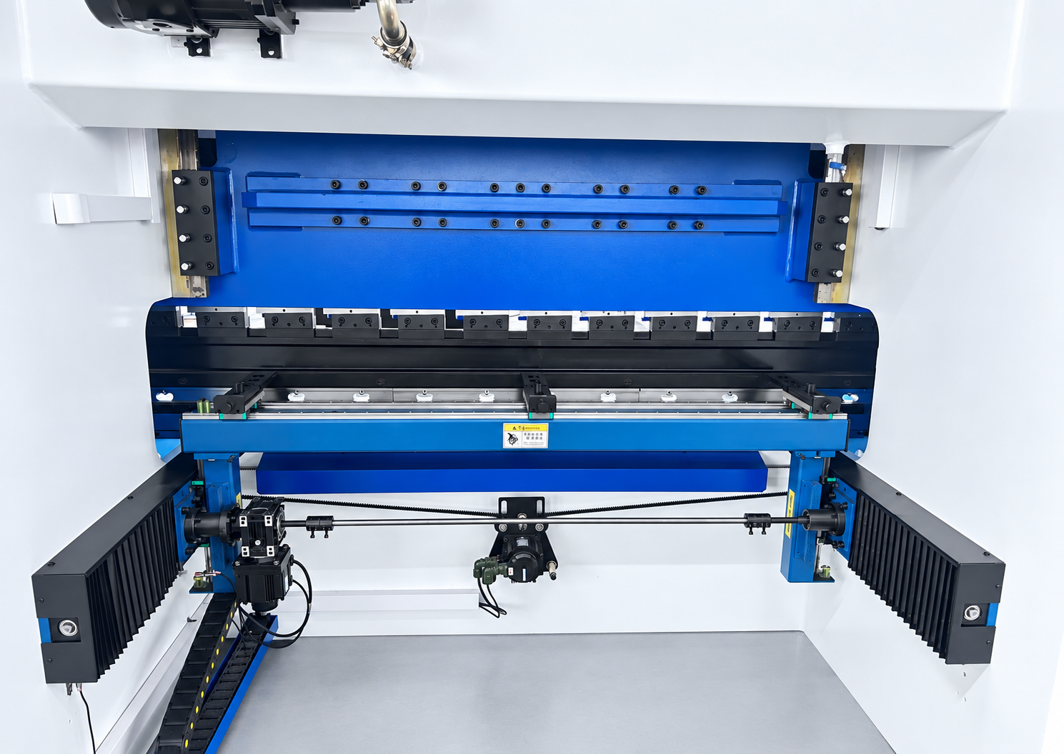
Rear-gauge fingers mounted on a press brakeComponent reference · final arrangement to be confirmed
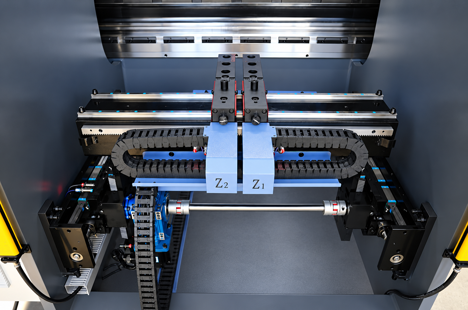
02 POSITIONING PATH

4-axis positioning

Independent-side movement review

Review additional independently controlled movement when stepped or asymmetric parts need more flexible positioning.

  • Map the bend sequence and reference edges
  • Confirm which movements are independent
  • Review finger spacing and collision clearance
Rear-gauge guide and drive assemblyComponent reference · final arrangement to be confirmed
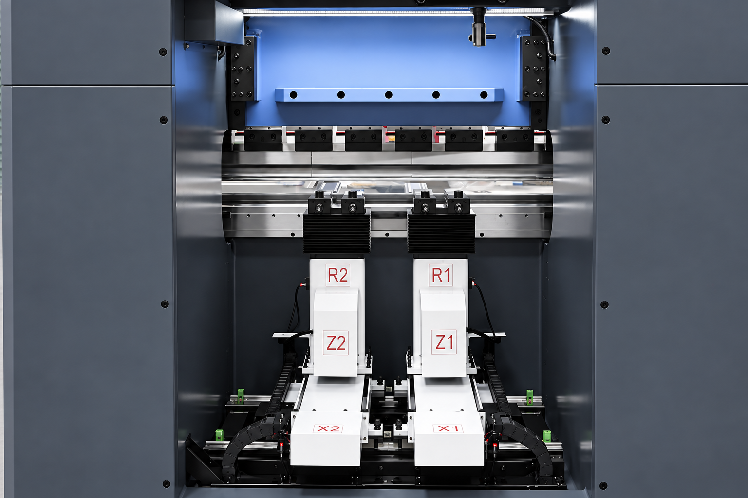
03 POSITIONING PATH

6-axis positioning

Multi-axis coordination review

For more involved parts, assess coordinated gauge movement, drive guidance and repeatable repositioning throughout the program.

  • Define required controlled movements by function
  • Check part rotation and regrip steps
  • Agree on datum, repeatability and acceptance method
Close view of a press-brake backgauge driveComponent reference · final arrangement to be confirmed
04 POSITIONING PATH

8-axis positioning

Application-specific scope review

A complex part may justify a broader machine-axis package. The exact rear-gauge axes and any ram or crowning axes must be specified separately.

  • List every axis and its physical function
  • Review controller, drive and program compatibility
  • Verify the final configuration in the technical proposal
Reading axis counts correctly

Y1/Y2 normally describe ram movement, while V can denote crowning. A total machine-axis count may include these functions; request an axis-by-axis list to identify the actual backgauge movements. Final availability and specifications require a GWMT technical review.

DRAWING-LED REVIEW

Get a backgauge plan for your part.

Share the part drawing, flange range, bend sequence, material and thickness, required accuracy and preferred controller or machine. We will review the positioning scope with you.