Product inquiries
All solutions

SOLUTION 05 · PRESS BRAKE TOOLING

Press Brake Tooling: Standard and Custom Punches, Dies & Accessories

Explore tooling profiles by forming task, then confirm dimensions and machine compatibility from your part drawing.

Explore tooling

TOOLING OVERVIEW

Standard and custom tools for sheet-metal bending

Upper punches, V-dies, multi-V dies, gooseneck profiles and specialized forming tools support different bending tasks. The punch and die need to be selected together for the part, material and machine.

A useful recommendation starts with the finished profile and bend sequence. Material thickness, bend angle, inside radius, working length, tool interface and handling requirements then shape the proposed set.

BEFORE YOU CHOOSE

What should a tooling review include?

Share these inputs so the proposed punch, die and clamping interface can be reviewed as one package:

  • Press-brake model and rated force
  • Required bending length
  • Material grade and thickness
  • Bend angle, inside radius and part drawing
  • Punch, die or special-forming requirement

TOOLING REFERENCE · 01

Standard tooling references for 100T & 125T press brakes

Compare the V-opening and punch profile against the forming task, material and machine interface.

Standard double-V die
Reference profile image · dimensions and supplied design are confirmed from the final drawing.

01 / 01

Standard double-V die

Two V-grooves provide alternative openings for compatible air-bending tasks. The selected groove is checked against sheet thickness, required radius and available loading.

  • Two opening choices within one die profile
  • Bend angle is controlled by the approved process and punch travel
Standard concentric four-V die
Reference profile image · dimensions and supplied design are confirmed from the final drawing.

01 / 02

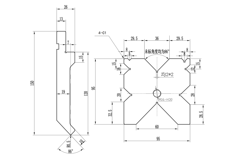
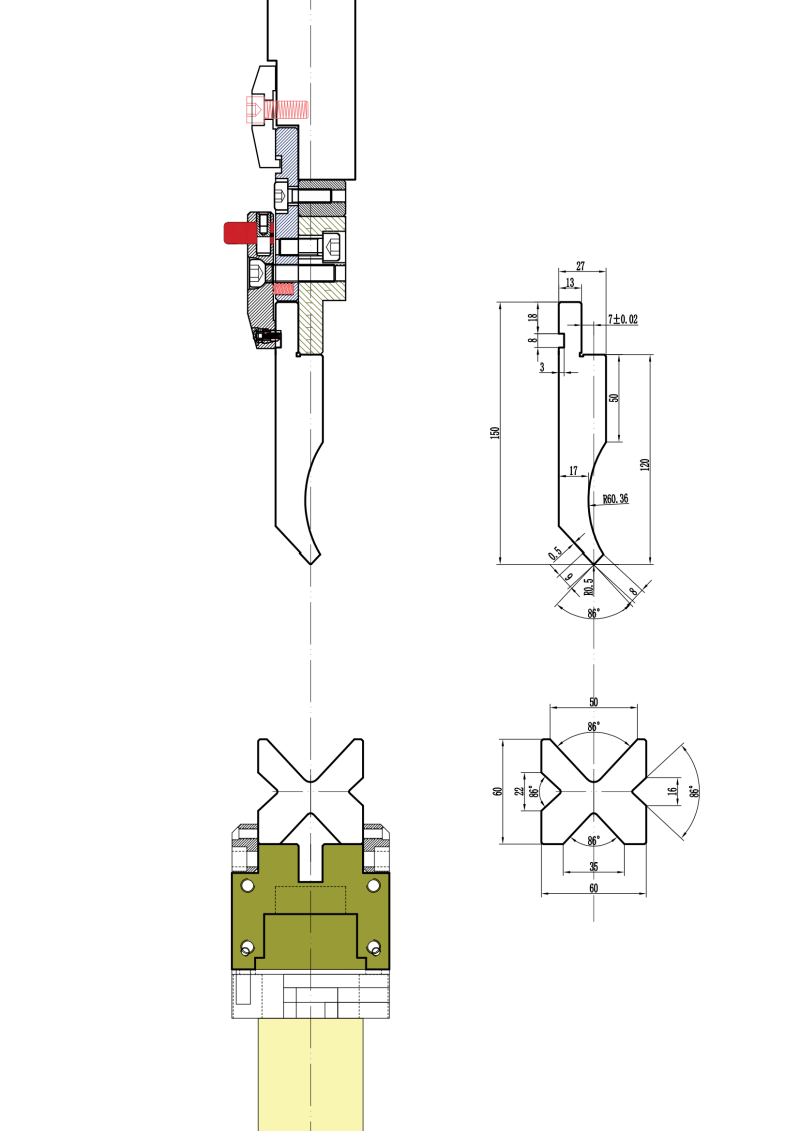
Standard concentric four-V die

A four-sided V profile offers several groove choices in one tool body. It can simplify changeovers when the relevant opening is suitable for the material and bend.

  • Multiple V-openings for different part conditions
  • Review groove geometry and permissible load before use
Standard multi-V die
Reference profile image · dimensions and supplied design are confirmed from the final drawing.

01 / 03

Standard multi-V die

Several V-openings allow one die to cover a range of compatible bend requirements. The working groove must be selected to suit the sheet and intended forming method.

  • Choose the opening from material, thickness and radius
  • Reduce tool changes only where the selected groove remains suitable

TOOLING REFERENCE · 02

Standard tooling references for 175T & 210T press brakes

These larger-machine examples still require a drawing-led check of load, length and clamping geometry.

Standard multi-V die
Reference profile image · dimensions and supplied design are confirmed from the final drawing.

02 / 01

Standard multi-V die

A multi-V die provides a choice of openings for varied bending conditions on larger equipment. Its drawing and section size are references, not a confirmed machine fit.

  • Match the groove to the required bend profile
  • Check length, interface and load distribution with the press brake
Standard double-V die
Reference profile image · dimensions and supplied design are confirmed from the final drawing.

02 / 02

Standard double-V die

The double-V arrangement offers two V-openings for different approved bends. Selection still depends on material, forming radius and tool load limits.

  • Two usable groove options subject to process review
  • Set-up and changeover depend on the machine and clamping system
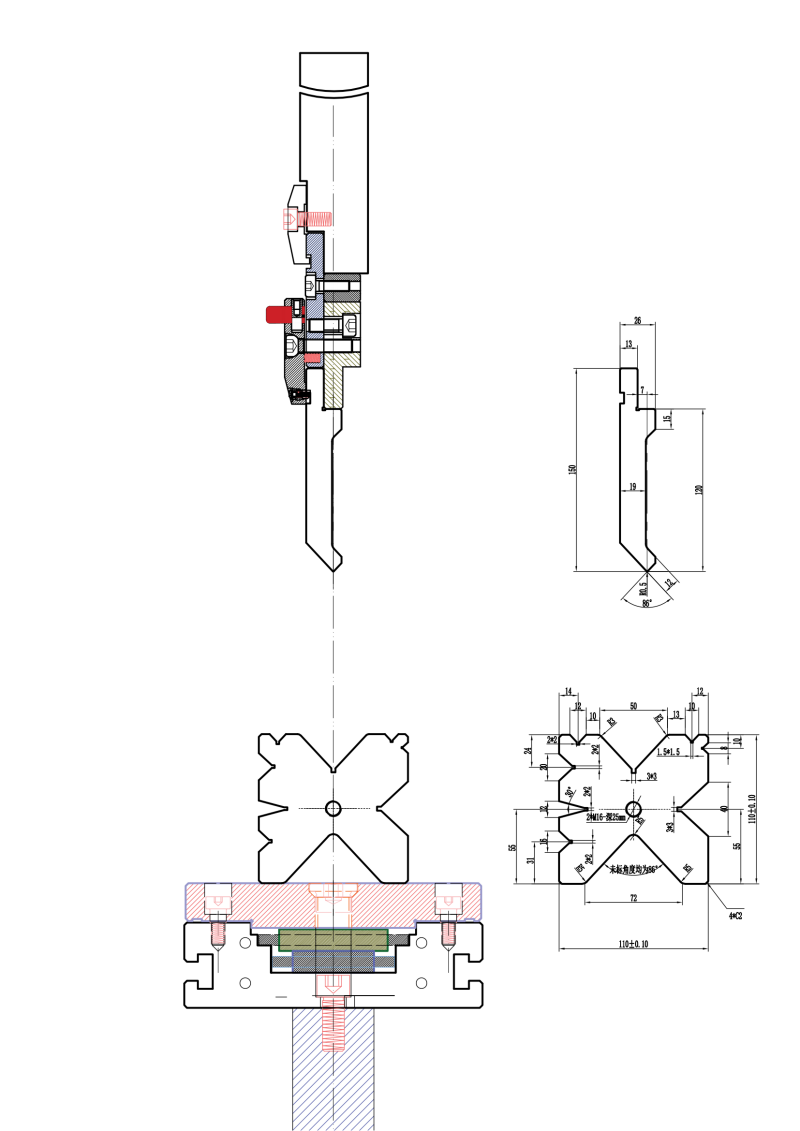
Standard four-V die
Reference profile image · dimensions and supplied design are confirmed from the final drawing.

02 / 03

Standard four-V die

Four V-grooves provide several forming choices in one die section. Confirm each groove with the representative part and the machine configuration.

  • Several openings in a compact die profile
  • Check geometry, support and tool capacity for each job

TOOLING REFERENCE · 03

Optional upper-punch profiles

Choose segmentation and clearance around the part geometry, bend sequence and tool-change workflow.

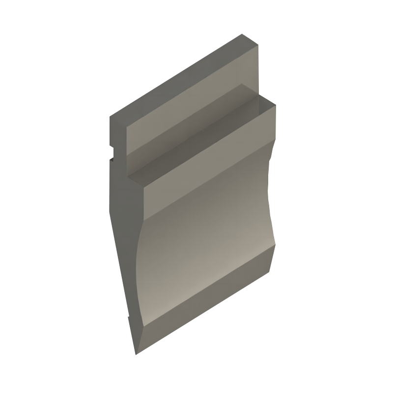
Segmented press-brake punch
Reference profile image · dimensions and supplied design are confirmed from the final drawing.

03 / 01

Segmented press-brake punch

Short tool sections can be combined to match different bend lengths and complex part layouts without handling one continuous punch.

  • Arrange sections around the needed work length
  • Review joint position, clamping and safe handling
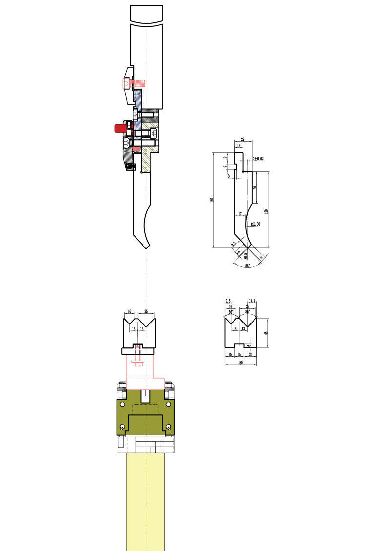
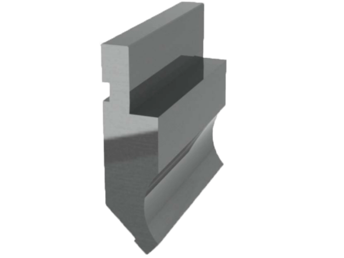
Gooseneck punch
Reference profile image · dimensions and supplied design are confirmed from the final drawing.

03 / 02

Gooseneck punch

The recessed profile creates clearance for flanges or return bends that may interfere with a straight punch during the forming sequence.

  • More room for channels, boxes and return flanges
  • Confirm the part envelope and approved tool loading
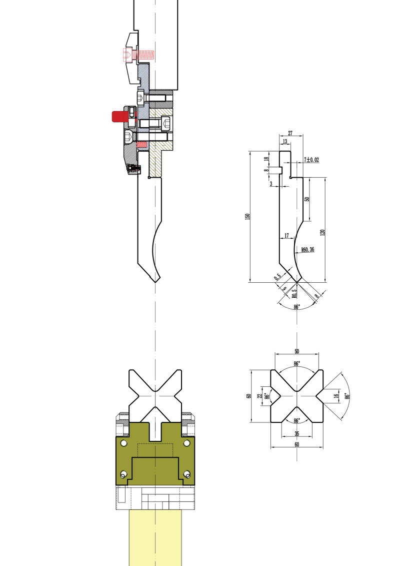
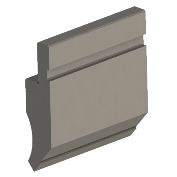
Wide-angle gooseneck punch
Reference profile image · dimensions and supplied design are confirmed from the final drawing.

03 / 03

Wide-angle gooseneck punch

A broader recessed profile may help with large-angle or offset geometries when the workpiece needs additional clearance around the punch.

  • Evaluate clearance through the full bend sequence
  • Check the specified angle and material before selecting a tool
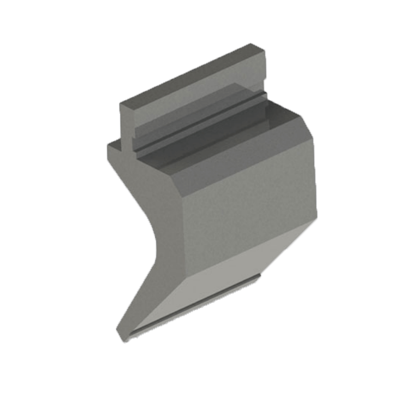
American-style punch
Reference profile image · dimensions and supplied design are confirmed from the final drawing.

03 / 04

American-style punch

This tooling profile is an interface option for compatible American-style clamping systems. It is not interchangeable until the holder, height and geometry are checked.

  • Review holder dimensions and clamping standard
  • Match the punch profile to the intended bend and radius

DRAWING-LED REVIEW

Turn the part drawing into a tooling set.

Send the press-brake model, material, thickness, bend length, radius, finished profile and current clamp information. We can review standard and custom tooling options with you.

The source grouping is a visual reference, not a GWMT load rating. Tool capacity and compatibility require a technical review.