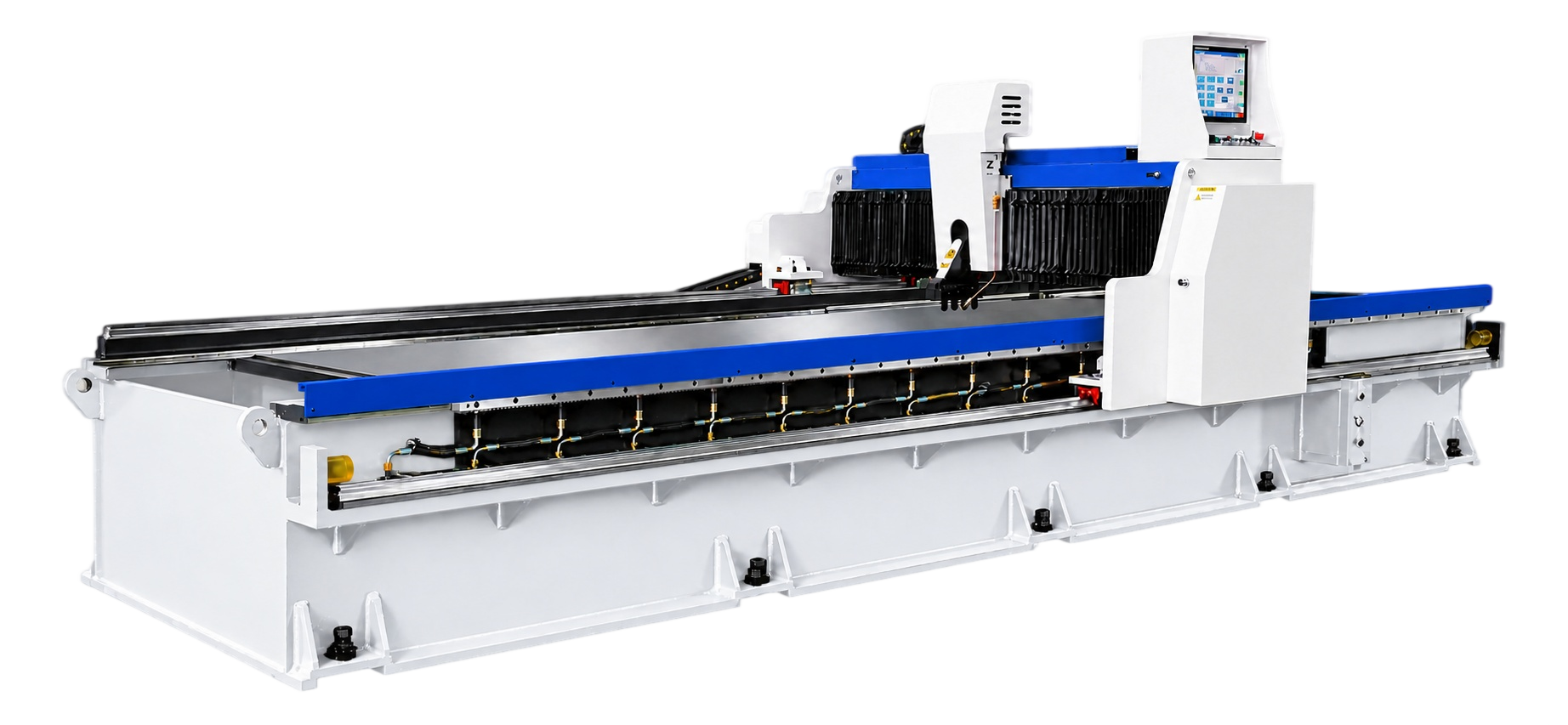
Gantry machine structure
The gantry arrangement provides a stable, open working area for sheet access, groove travel, loading, and unloading planning.
A gantry-type CNC V-grooving platform for controlled fold preparation, sharp visual lines, and high-finish sheet-metal work.
PRODUCT OVERVIEW
The GW platform creates programmed V-grooves at defined positions so sheet material can be prepared for controlled bending and appearance-critical forming. The panel, groove layout, residual material, and downstream bend sequence are reviewed together.
DETAILED DESIGN & COMPONENTS
The gantry arrangement provides a stable, open working area for sheet access, groove travel, loading, and unloading planning.
Programmed axes coordinate groove position, sequence, and travel so the process can be reviewed against the required bend layout.
Tool-holder movement, V-groove geometry, and cutting-tool selection are matched to material, surface condition, residual thickness, and appearance target.
Clamping and support are planned around panel stiffness, protected finishes, groove path, and stable sheet positioning.
Table condition, panel reference, and alignment method are considered with visible surface protection and repeated position accuracy.
Loading space, guarding, control access, chip management, and service clearance are coordinated with the factory workflow.
WHY THIS PROCESS
Review groove depth, residual material, and bend sequence together where a small radius or controlled external line matters.
Use drawing dimensions and visible surfaces to organize groove positions, repeat programs, and the subsequent bend process.
Coordinate loading, panel support, chip handling, and downstream forming rather than treating the groove as an isolated operation.
Reference values for the GW 1250 × 4000 platform. Final capacity, sheet-flatness conditions, options, and acceptance criteria are confirmed in the technical agreement.
| Item | Unit | Reference value |
|---|---|---|
| Max. sheet width | mm | 1,250 |
| Max. sheet length | mm | 4,000 |
| Max. thickness (stainless-steel reference) | mm | 4 |
| Min. sheet thickness | mm | 0.6 |
| Min. V-groove distance from edge | mm | 8 |
| Max. X-axis cutting speed | m/min | 40 |
| Max. X-axis return speed | m/min | 50 |
| Y1 tool-holder lateral travel | mm | 1,250 |
| Y1 tool-holder resolution | mm | ±0.01 |
| Y-axis positioning accuracy | mm | ±0.05 |
| Z-axis vertical resolution | mm | ±0.01 |
| Z-axis positioning accuracy | mm | ±0.05 |
| X-axis motor power | kW | 4.5 |
| Y1 tool holder / Y2 hold-down servo power | kW | 1 (combined reference) |
| Z-axis servo motor power | kW | 1 |
| Machine dimensions (L × W × H) | mm | 6,100 × 2,300 × 1,560 |
| Table flatness | mm | ≤0.05 |
The 4 mm maximum thickness is a stainless-steel catalog reference. Resolution and positioning accuracy describe separate specifications. Final performance is subject to the agreed configuration and material conditions.
TAILORED TECHNICAL PROPOSAL
Share drawings, materials, target output, and current process constraints. An engineer can use them to prepare the next conversation.