
01
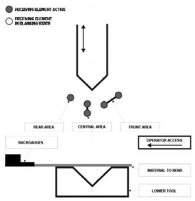
Full detection area
Front, central and rear sensing zones are shown active in this reference configuration.
SOLUTION 03 · PRESS BRAKE SAFETY
Explore DSP, MSD, SDKELI and LN protection references, sensing-zone diagrams and installation examples. The final safety function must be matched to the machine, tools and production task.
01 · DSP LASER PROTECTION
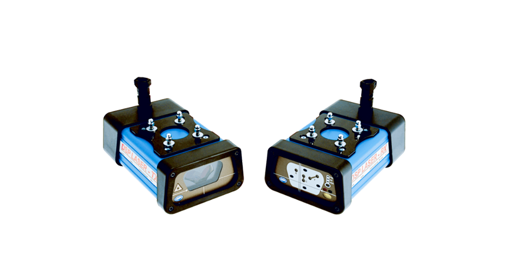
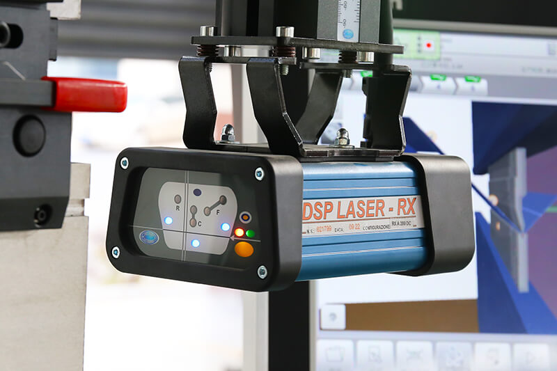
The DSP reference places a monitored area beneath the moving upper tool. During the fast approach, an object entering that area is detected before it reaches the tool tip; the device signal must then be handled by the press brake’s verified safety function. Tooling, part shape and stopping performance determine the final arrangement.
DSP PROTECTION AREA
These manufacturer reference drawings explain how the front, central and rear areas may be considered. They are not operating instructions; any mode and blanking setting require a qualified, task-specific safety assessment.
Front, central and rear sensing zones are shown active in this reference configuration.
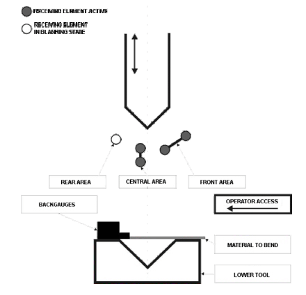
A reduced sensing arrangement can be considered for formed or boxed parts only after a task-specific safety review.
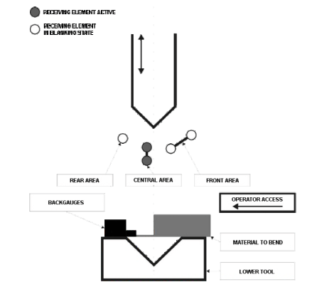
The diagram illustrates another reference zone arrangement; its permitted use must be confirmed for the actual machine and process.
DSP DEVICE & INSTALLATION
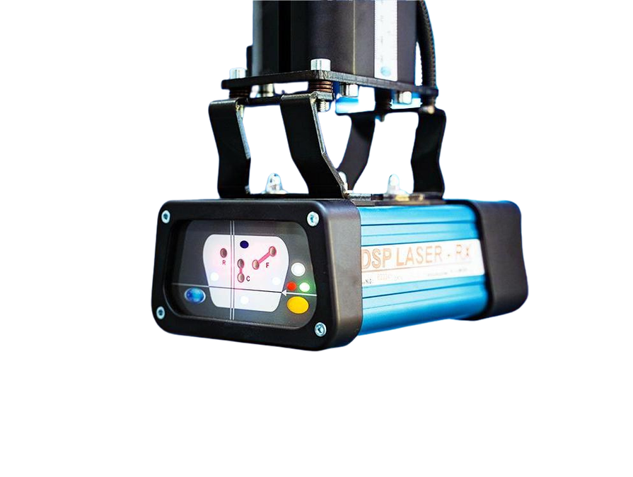
The reference device is mounted close to the press-brake tooling so its detection field can move with the upper beam. The usable mode, sensing distance and stop response must be checked against the selected device documentation and the actual machine.
02 · SINGLE-BEAM REFERENCE
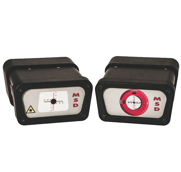
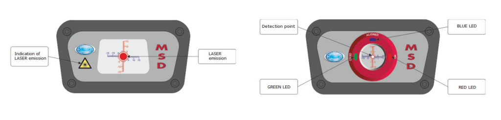
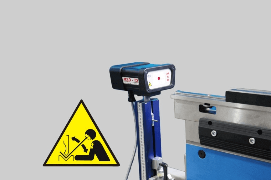
The MSD reference uses a visible laser beam between a transmitter and receiver. An interruption inside the defined detection area is passed to the machine safety system, which must be designed and validated for the particular press brake.
03 · TOOL-AREA REFERENCE
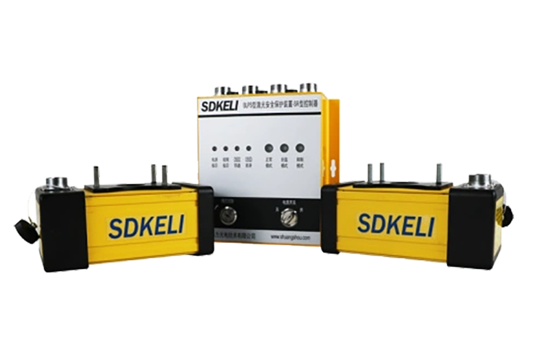
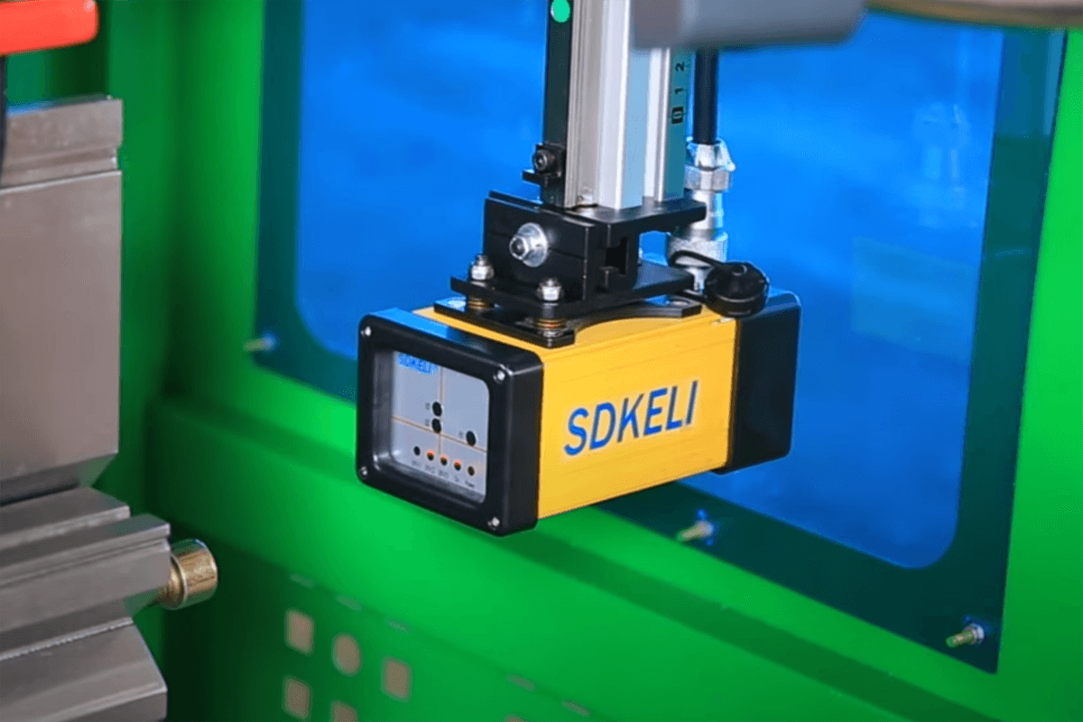
The SDKELI reference places a laser-sensing arrangement close to the moving upper tool. Its controller, sensing field and mounting position are reviewed with the actual tool geometry and machine interface.
04 · PHOTOELECTRIC REFERENCE
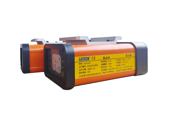
The LN reference focuses on monitoring the upper-tool tip area where the operator approaches the bending zone. Selection has to balance access, part handling and the verified stopping behavior of the press brake.
ASSESSMENT CONTEXT
Start with the task that most closely represents your daily production. The selected context organizes the evidence needed for an engineering discussion; it does not define a safety operating mode.
01 · SELECTION REVIEW
Review the recurring tooling, part size and expected production rhythm before selecting any tool-area protection arrangement.
SAFETY PROJECT INPUTS
Share the press-brake model, year, tooling information, representative parts, existing safeguarding, drawings, photos and the applicable market or project requirements. GWMT can then discuss the appropriate next technical review.