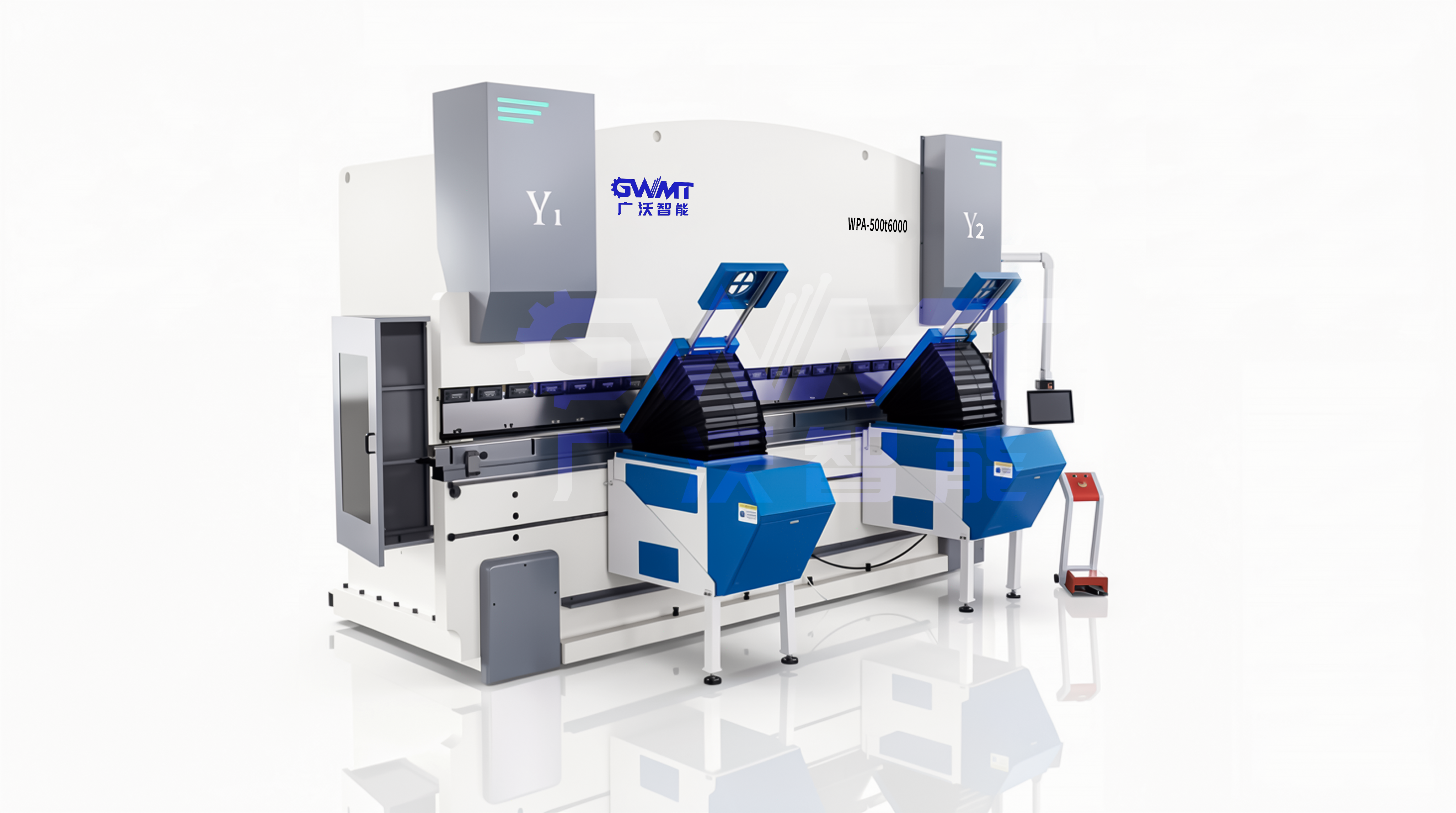
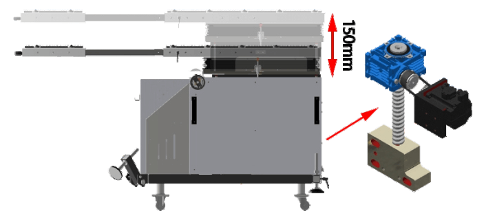
GWMT WPA-500T6000 follower-support application illustration; confirm the support path and part envelope for the configured machine.View original image
As a large sheet rises during bending, its contact points and center of gravity change. A CNC follower table supports that movement, helping reduce sustained manual holding and organize loading, bending and removal around the actual part.
A following arrangement can coordinate with the press brake Y-axis using position feedback such as a linear scale. Independent controls and adjustable support positions can accommodate tooling height and die openings. Brush surfaces help limit scuffing; moving, removing or sharing units between machines requires confirmed mechanical interfaces, control signals and available space.
Two follower-support arrangements
Choose the working layout around part weight, bend sequence and available space.
Floor-mounted
A separate support unit in front of the press brake provides a base for handling larger sheets. Review floor conditions, table height, part balance and tooling clearance together, rather than selecting by load alone.
Coordinate the support units with the machine working area to suit the part mix and workshop layout. Review coordination between units, synchronization interfaces and loading paths before confirming unit count and installation.
GWMT support-layout illustration, not a UP-series unit photographExplore arrangement
Floor-mounted bending follower
These model identifiers, figures and illustrations are source-reference examples, not confirmed GWMT specifications, availability or compatibility. Validate the conditions for load, angle and travel separately; their maxima do not establish a simultaneous operating rating.
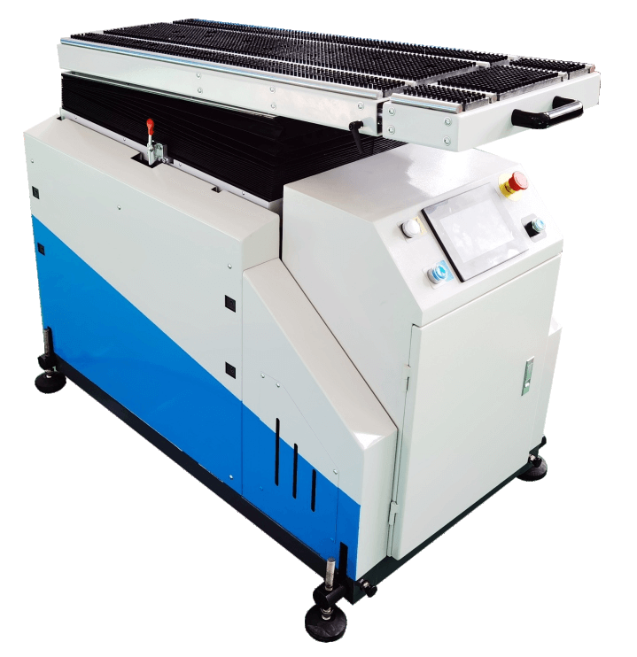
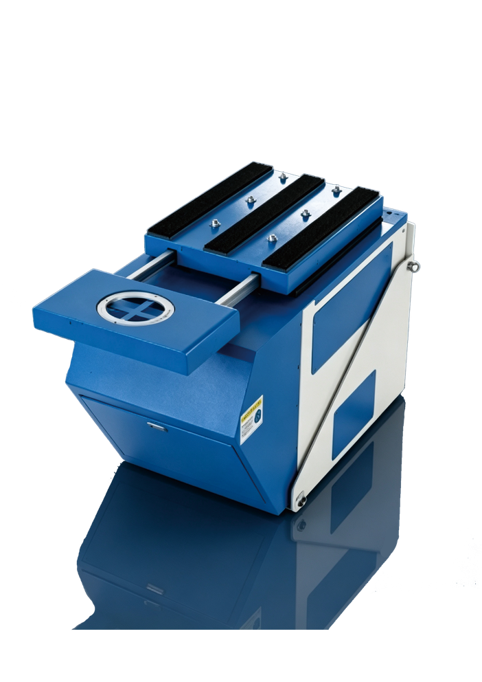
Original unbranded appearance reference; the technical proposal defines the final equipment.View original image
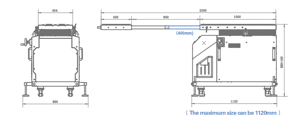
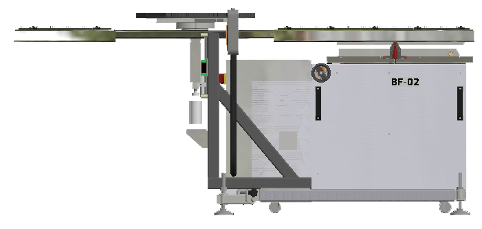
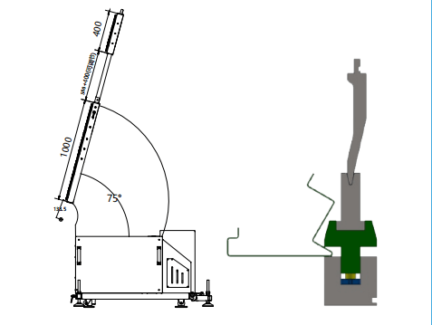
The original drawing retains extended positions, base dimensions and English annotations. Lengths describe different states and must not be treated as one installation envelope; use the approved project drawing for dimensions and adjustment ranges.View original image
Main structure
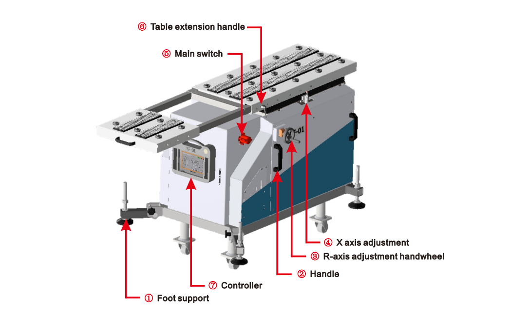
This diagram identifies components; it does not replace installation, commissioning or safe-operation instructions.View original image
Foot supports:Provide leveling and stable support. Qualified personnel must confirm adjustments in the specified safe machine state using the equipment instructions.
Transport handle:Provides a handhold for relocating the unit. Check weight, floor conditions and locking state; it is not an approved lifting point unless specifically confirmed.
R-axis adjustment handwheel:Sets table height relative to the lower tooling area. The reference describes approximately 1 mm rise per turn; validate the transmission ratio and range for the selected unit.
X-axis adjustment handle:Adjusts table position to suit the sheet contact path. The reference mentions approximately 120 mm from the outer die V-opening edge; this is not a universal safe clearance. Confirm the setting through interference and safety assessment.
Main switch:Controls power availability. Energizing the unit does not authorize movement; check operating conditions, interlocks and emergency-stop status against the actual controls.
Table extension handle:Locks or releases the telescoping table section to adjust the support area. Review load and clearance in the extended position separately.
CNC controller:Sets and manages following movements. Position feedback, machine communications and available functions depend on the validated control configuration.
Optional configurations
Discuss these options around the part and machine; confirm availability and integration separately.
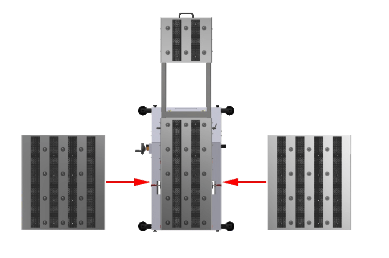
Expandable worktable
Increase the sheet contact area while checking support conditions and load distribution in the extended state.
These model identifiers, figures and illustrations are source-reference examples, not confirmed GWMT specifications, availability or compatibility. Validate the conditions for load, angle and travel separately; their maxima do not establish a simultaneous operating rating.
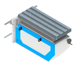
GWMT follower-accessory appearance illustration; not a photograph of model UP180.View original image
Prepare the press-brake model, tooling information, material and thickness, part dimensions and weight, bend sequence and site layout so the support discussion starts with the real task.