Punching station
Punch, die, worktable, guides, material strength, hole diameter, and thickness must be checked together for the required hole-making task.
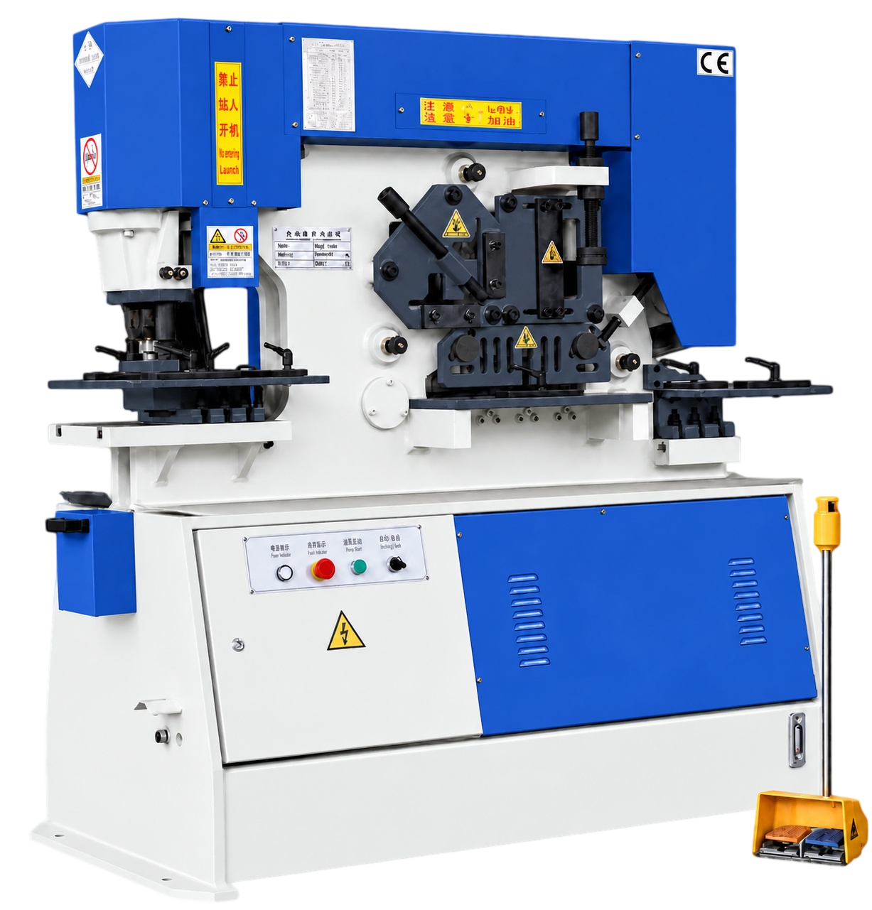
A multi-station hydraulic platform for punching, flat-bar shearing, section cutting, angle processing, and notching in practical fabrication workflows.
PRODUCT OVERVIEW
The Q35Y family combines core punching and shearing workstations in one machine. The right model, tooling, stops, material supports, and operating method are reviewed against the actual profile schedule rather than a single maximum number.
WORKSTATIONS & COMPONENTS
Punch, die, worktable, guides, material strength, hole diameter, and thickness must be checked together for the required hole-making task.
Flat-bar capacity is assessed as a thickness-and-width pair, with support and stop requirements defined for the cut schedule.
Angle size, wall thickness, cut orientation, tooling, and the required repeat stop are reviewed before the scope is set.
Section geometry and stock size determine the compatible station, blade arrangement, support, and safe material handling.
Notch geometry, material, finish expectation, and downstream fit-up establish the appropriate tooling and operation.
Foot control, guards, work-zone access, lubrication, electrical scope, and service access are coordinated with the intended workflow.
WHY A MULTI-STATION ROUTE
Bring repeat punching, bar cutting, angle processing, and notching into one planned work area when the daily mix benefits from shared preparation.
Select punch, die, blades, stops, and supports against each task—capacity is not a transferable single number across stations.
Coordinate material support, repeat stops, discharge space, guarding, and work order so every station fits the workshop routine.
Source material strength: ≤450 N/mm². Punch force retains unit T. Flat-bar ratings are separate thickness/width pairs; confirm hole diameter and thickness together. Joist and channel capacities require special order confirmation.
| Model | Punching pressure T | Max. cutting thickness mm | Plate strength N/mm² | Shear angle ° | Flat bar 1 mm | Flat bar 2 mm | Slider travel mm | Trips frequency times/min | Throat depth mm | Punch depth mm | Max. punching dia. mm | Main motor kW | Overall dimensions L × W × H / mm |
|---|---|---|---|---|---|---|---|---|---|---|---|---|---|
| Q35Y-12 | 35 | 12 | ≤450 | 7° | 12×160 | 6×300 | 35 | 10–18 | 115 | 12 | 25 | 4 | 950×550×1800 |
| Q35Y-16 | 60 | 16 | ≤450 | 7° | 16×250 | 8×400 | 80 | 11–20 | 300 | 16 | 25 | 5.5 | 1740×810×1830 |
| Q35Y-20 | 90 | 20 | ≤450 | 8° | 20×330 | 10×480 | 80 | 12–20 | 355 | 20 | 30 | 7.5 | 1950×900×1950 |
| Q35Y-25 | 120 | 25 | ≤450 | 8° | 25×330 | 16×600 | 80 | 8–18 | 400 | 25 | 35 | 11 | 2355×960×2090 |
| Q35Y-30 | 160 | 30 | ≤450 | 8° | 30×335 | 20×600 | 80 | 6–16 | 600 | 28 | 38 | 15 | 2800×1050×2450 |
| Q35Y-40 | 200 | 40 | ≤450 | 8° | 40×335 | 30×600 | 100 | 6–16 | 530 | 35 | 40 | 18.5 | 2900×1100×2500 |
| Q35Y-50 | 250 | 50 | ≤450 | 8° | 50×300 | 30×750 | 100 | 6–12 | 600 | 40 | 45 | 18.5 | 3200×1440×2500 |
| Model | Round bar mm | Square bar mm | Equal angle 90° mm | Equal angle 45° mm | T-bar 90° mm | T-bar 45° mm | Joist mm | Channel mm |
|---|---|---|---|---|---|---|---|---|
| Q35Y-12 | 35 | 30×30 | 86×86×8 | — | — | — | — | — |
| Q35Y-16 | 45 | 40×40 | 120×120×12 | 50×50×5 | 125×125×12 | 60×60×8 | 120×74×5 | 120×53×5.5 |
| Q35Y-20 | 50 | 50×50 | 140×140×12 | 70×70×10 | 140×140×12 | 70×70×10 | 160×88×6 | 160×63×6.5 |
| Q35Y-25 | 60 | 50×50 | 160×160×14 | 60×60×6 | 160×160×14 | 80×80×10 | 200×102×9 | 200×75×9 |
| Q35Y-30 | 65 | 55×55 | 180×180×16 | 80×80×8 | 180×180×16 | 80×80×10 | 280×124×10.5 | 280×86×11.5 |
| Q35Y-40 | 70 | 60×60 | 200×200×18 | 80×80×10 | 200×200×18 | 100×100×10 | 300×130×13 | 300×89×11.5 |
| Q35Y-50 | 80 | 65×65 | 200×200×18 | 100×100×10 | 200×200×18 | 120×120×12 | 320×130×13 | 320×92×12 |
TAILORED TECHNICAL PROPOSAL
Share drawings, materials, target output, and current process constraints. An engineer can use them to prepare the next conversation.