
Machine frame and motion base
The frame, guide arrangement, drive system, and usable work zone are planned together for sheet format, production rhythm, and access.
A sheet-format fiber laser platform for precise profile cutting, digital nesting, and a production flow configured around the materials you actually process.
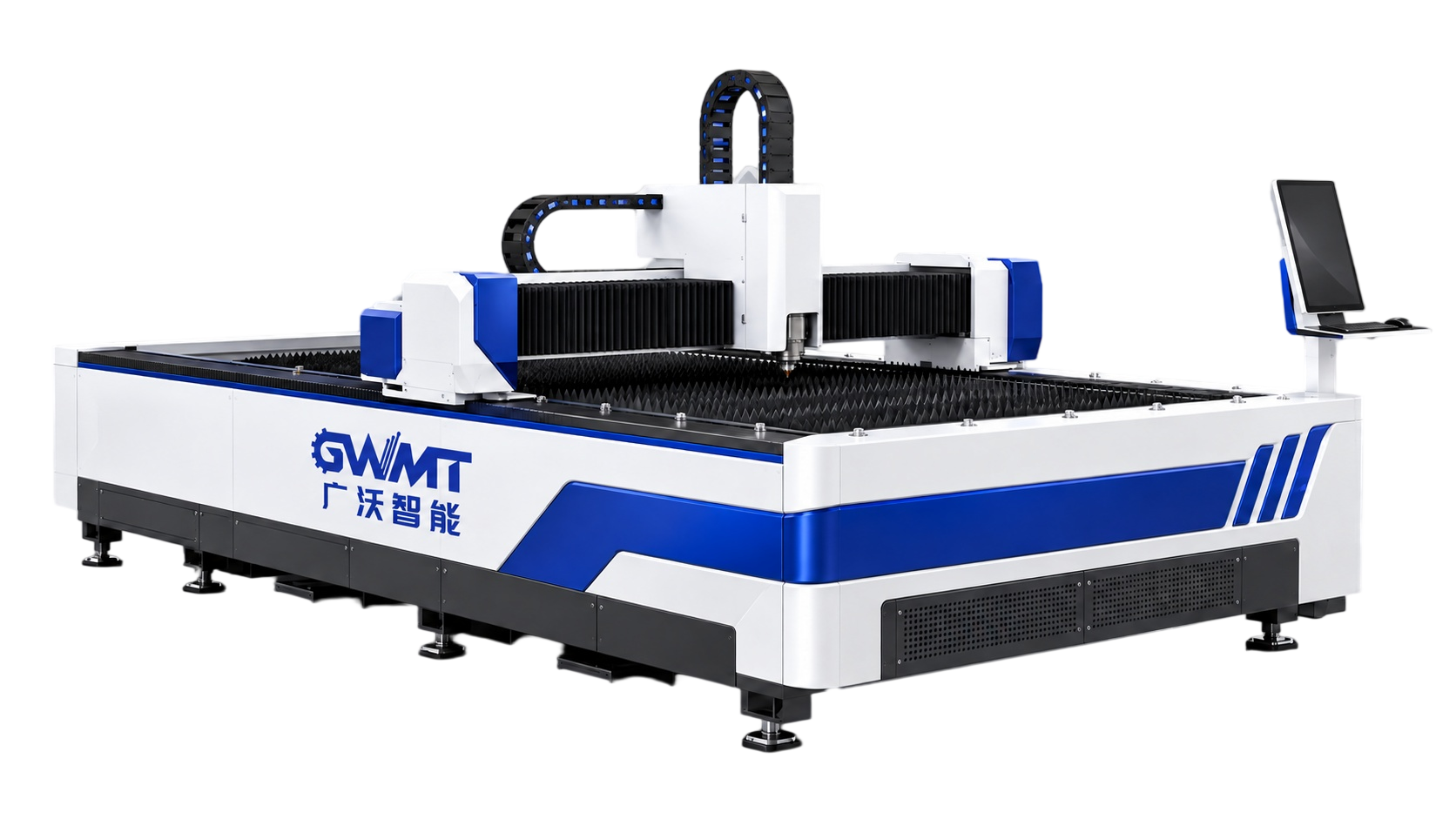
PRODUCT OVERVIEW
The 3015 is built around a 3,000 × 1,500 mm planning format. Source selection, cutting head, controls, assist gas, extraction, and sheet handling are reviewed as one process—not as isolated options.
DETAILED DESIGN & COMPONENTS
The frame, guide arrangement, drive system, and usable work zone are planned together for sheet format, production rhythm, and access.
Head selection, auto-focus behavior, nozzle setup, and collision protection are confirmed around the material range and intended edge quality.
Laser-source range is matched to material mix, thickness distribution, part features, and the required production plan.
Control, nesting, program preparation, and operator handoff are reviewed to support repeatable production from drawing to cut part.
Gas supply, extraction, duct routing, and housekeeping requirements are defined with the material, cutting process, and factory layout.
Loading method, unloading route, workholding, guarding, and service access are coordinated with the available floor space.
CONFIGURE FROM THE PART
A useful laser proposal begins with the part and its production route. These three inputs establish the first technical conversation.
Share grades, frequent and maximum thicknesses, surface requirements, and reflective materials.
Provide representative DXF or drawings, smallest features, pierce expectations, tolerances, and nesting priorities.
Confirm sheet formats, loading method, available footprint, extraction route, downstream handling, and target output.
AUTOMATION READINESS
Manual loading may be suitable for flexible production. When volume, sheet weight, or unattended flow changes, loading, unloading, storage, and downstream sorting should be reviewed as part of the same cell.
A cross-model planning reference. Power, configuration, safety, material performance, and final acceptance are confirmed in the technical agreement.
| Model | 3015 | 4015 | 4020 | 6015 | 6020 | 6025 | 8025 | 12025 |
|---|---|---|---|---|---|---|---|---|
| Processing range | 3,000 × 1,500 mm | 4,000 × 1,500 mm | 4,000 × 2,000 mm | 6,000 × 1,500 mm | 6,000 × 2,000 mm | 6,000 × 2,500 mm | 8,000 × 2,500 mm | 12,000 × 2,500 mm |
| X-axis travel | 1,500 mm | 1,500 mm | 2,000 mm | 1,500 mm | 2,000 mm | 2,500 mm | 2,500 mm | 2,500 mm |
| Y-axis travel | 3,000 mm | 4,000 mm | 4,000 mm | 6,000 mm | 6,000 mm | 6,300 mm | 8,000 mm | 12,000 mm |
| Z-axis travel | 250 mm | 250 mm | 250 mm | 250 mm | 250 mm | 250 mm | 250 mm | 250 mm |
| Laser power | 1,000 W–20,000 W | |||||||
| X/Y positioning accuracy | ≤±0.03 mm/min | |||||||
| X/Y repeat positioning accuracy | ≤±0.02 mm/min | |||||||
| Max. positioning speed | 120 m/min | |||||||
Catalog values are planning references. Source power is a series range, and accuracy performance must be confirmed for the selected configuration, material, process gas, and installation conditions.
TAILORED TECHNICAL PROPOSAL
Share drawings, materials, target output, and current process constraints. An engineer can use them to prepare the next conversation.