
Four-column guidance
Columns, table, slide travel, and tooling envelope are reviewed together for load path and part access.
A four-column hydraulic platform for forming, drawing, straightening, assembly, and general pressing work, configured around the force curve, tooling envelope, loading method, and safety scope.
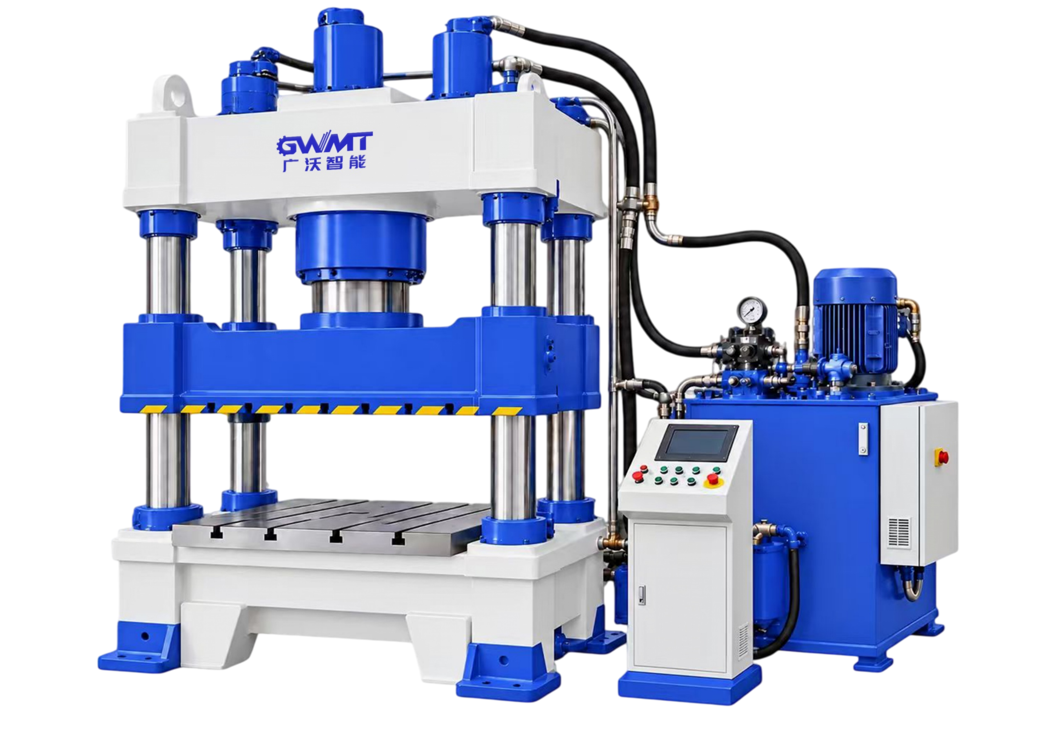
A four-column hydraulic platform for forming, drawing, straightening, assembly, and general pressing work, configured around the force curve, tooling envelope, loading method, and safety scope.
Columns, table, slide travel, and tooling envelope are reviewed together for load path and part access.
Pressure, approach, pressing, and return phases are selected around the actual process cycle.
Tool dimensions, daylight, stroke, table size, loading, and part removal establish usable capacity.
Control scope, dwell, pressure profile, sequence, and verification needs are matched to the production task.
Loading, support, ejection method, discharge, and lifting plan are reviewed with part weight and workflow.
Guarding, access, maintenance space, and operating procedure are confirmed as part of the installation.
Catalog values are planning references. Final force, ejector scope, tooling, hydraulic configuration, safety, and acceptance are confirmed in the technical agreement.
| Technical parameter | Unit | YWF32-40 | YWF32-63 | YWF32-100 | YWF32-100A | YWF32-160 | YWF32-160B | YWF32-200 | YWF32-200A | YWF32-315A | YWF32-315B | YWF32-400 | YWF32-500 | YWF32-500C | YWF32-630 | YWF32-800 | YWF32-1000 | YWF32-1250 | YWF32-1600 |
|---|---|---|---|---|---|---|---|---|---|---|---|---|---|---|---|---|---|---|---|
| Rated force | kN | 400 | 630 | 1000 | 1000 | 1600 | 1600 | 2000 | 2000 | 3150 | 3150 | 4000 | 5000 | 5000 | 6300 | 8000 | 10000 | 12500 | 16000 |
| Maximum liquid pressure | MPa | 25 | 25 | 25 | 25 | 25 | 25 | 25 | 25 | 25 | 25 | 25 | 25 | 25 | 25 | 25 | 25 | 25 | 25 |
| Ejector force | kN | 120 | 190 | 190 | 190 | 400 | 400 | 400 | 400 | 630 | 630 | 630 | 1000 | 1000 | 1000 | 1600 | 1600 | 1600 | 2000 |
| Maximum slide stroke | mm | 450 | 500 | 600 | 600 | 700 | 700 | 700 | 700 | 800 | 800 | 800 | 900 | 900 | 900 | 900 | 900 | 900 | 900 |
| Maximum ejector stroke | mm | 150 | 200 | 200 | 200 | 200 | 200 | 250 | 250 | 300 | 300 | 300 | 350 | 350 | 350 | 350 | 350 | 400 | 400 |
| Daylight | mm | 750 | 750 | 880 | 880 | 1000 | 1000 | 1100 | 1100 | 1000 | 1250 | 1250 | 1500 | 1500 | 1500 | 1500 | 1500 | 1500 | 1500 |
| Slide approach speed | mm/s | 160 | 180 | 120 | 120 | 100 | 100 | 100 | 100 | 100 | 100 | 100 | 100 | 100 | 80 | 80 | 80 | 80 | 80 |
| Slide pressing speed | mm/s | 20–25 | 15–20 | 10–14 | 10–14 | 10–15 | 10–15 | 10–15 | 10–15 | 8–12 | 8–12 | 6–10 | 10–15 | 10–15 | 6–10 | 12–15 | 10–12 | 8–10 | 6–8 |
| Slide return speed | mm/s | 120 | 100 | 120 | 120 | 70 | 70 | 70 | 70 | 60 | 60 | 55 | 70 | 70 | 60 | 70 | 70 | 55 | 40 |
| Effective table area L–R | mm | 500 | 580 | 720 | 1000 | 720 | 1000 | 1000 | 1000 | 1200 | 1260 | 1240 | 1400 | 2400 | 1500 | 1600 | 1600 | 1700 | 1600 |
| Effective table area F–B | mm | 460 | 500 | 580 | 800 | 620 | 800 | 900 | 1200 | 1200 | 1400 | 1200 | 1400 | 1400 | 1500 | 1600 | 1600 | 1600 | 1600 |
| Motor power | kW | 5.5 | 7.5 | 7.5 | 7.5 | 11 | 11 | 15 | 15 | 11 | 11 | 15 | 2×22 | 2×22 | 2×22 | 2×30 | 2×30 | 2×37 | 2×37 |
TAILORED TECHNICAL PROPOSAL
Share drawings, materials, target output, and current process constraints. An engineer can use them to prepare the next conversation.