
Guillotine frame structure
The frame and upper-beam arrangement are selected for the planned plate duty, working length, operating method, and required cutting geometry.
structureA guillotine-style hydraulic shear for controlled cutting geometry and demanding plate work, configured around the material schedule and required downstream quality.
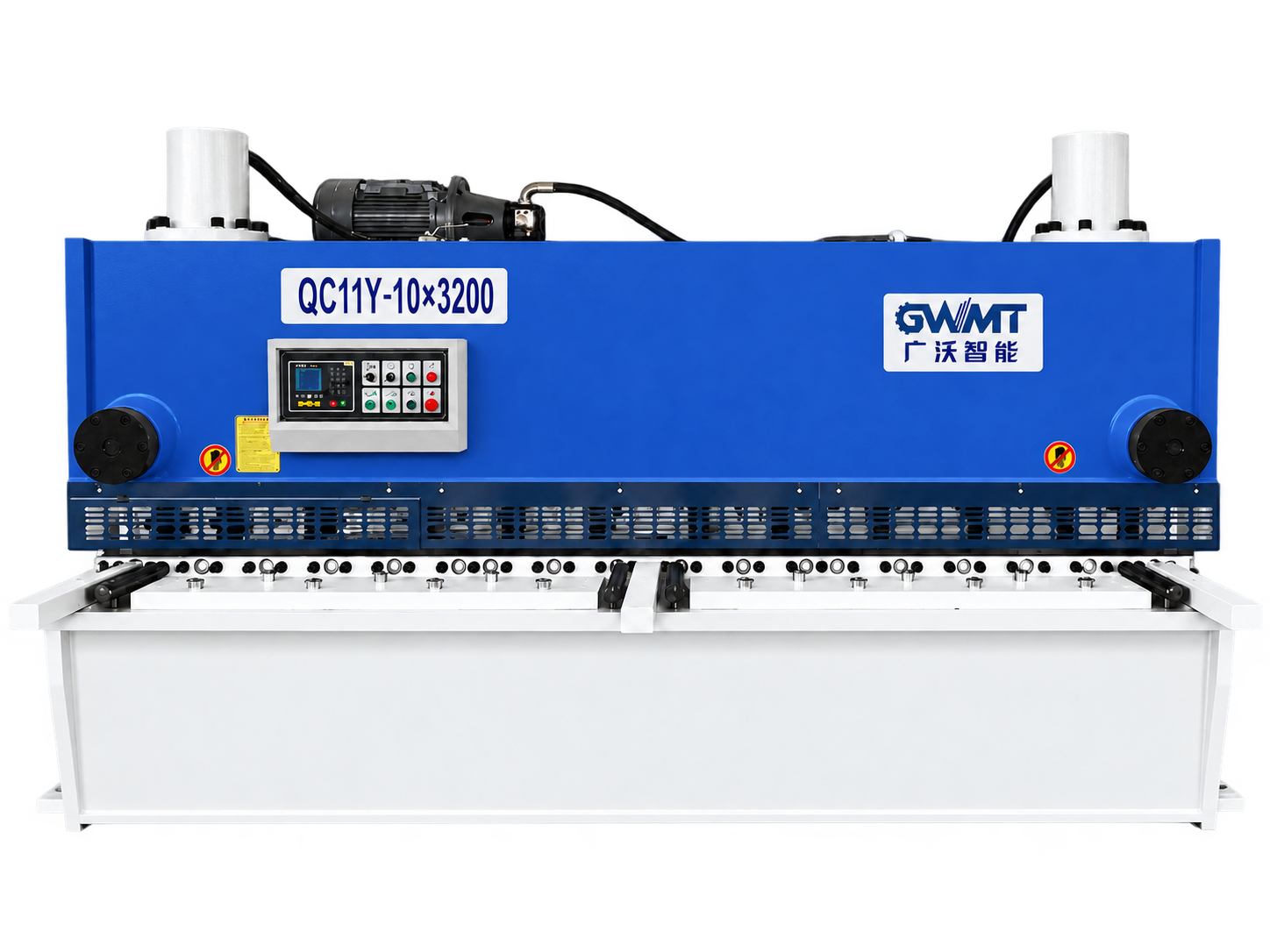
PRODUCT OVERVIEW
The guillotine platform supports a structured approach to blade clearance, cut-angle setting, backgauge positioning, sheet support, controls, and safety planning.
CONFIGURATION POINTS
The frame and upper-beam arrangement are selected for the planned plate duty, working length, operating method, and required cutting geometry.
structureBlade clearance and knife condition are reviewed against thickness, material grade, edge requirement, and the expected production mix.
bladePositioning travel, finger arrangement, and programmed retraction can be defined around repeat cut dimensions and discharge access.
positioningThe required cutting cycle is reviewed with sheet width, material behavior, noise expectations, and the intended production rhythm.
driveFront arms, squaring references, support balls, and length stops can be matched to the sheet format and operator method.
supportGuarding, work-zone access, electrical layout, hydraulic service points, and maintenance access are reviewed before configuration approval.
safetyDesigned to deliver reliable performance across a range of fabrication requirements.
| Model | Shearing thickness mm | Shearing width mm | Strokes min⁻¹ | Backgauge range mm | Shearing angle ° | Main power kW |
|---|---|---|---|---|---|---|
| QC11Y/K-6×2500 | 6 | 2500 | 16–35 | 20–580 | 30′–1°30′ | 7.5 |
| QC11Y/K-6×3200 | 6 | 3200 | 14–35 | 20–580 | 30′–1°30′ | 7.5 |
| QC11Y/K-6×4000 | 6 | 4000 | 10–30 | 20–580 | 30′–1°30′ | 7.5 |
| QC11Y/K-6×5000 | 6 | 5000 | 10–30 | 20–800 | 30′–1°30′ | 11 |
| QC11Y/K-6×6000 | 6 | 6000 | 8–25 | 20–800 | 30′–1°30′ | 11 |
| QC11Y/K-8×2500 | 8 | 2500 | 14–30 | 20–600 | 30′–1°30′ | 11 |
| QC11Y/K-8×3200 | 8 | 3200 | 12–30 | 20–600 | 30′–1°30′ | 11 |
| QC11Y/K-8×4000 | 8 | 4000 | 10–25 | 20–600 | 30′–1°30′ | 11 |
| QC11Y/K-8×5000 | 8 | 5000 | 10–25 | 20–800 | 30′–1°30′ | 15 |
| QC11Y/K-8×6000 | 8 | 6000 | 8–20 | 20–800 | 30′–1°30′ | 15 |
| QC11Y/K-12×2500 | 12 | 2500 | 12–25 | 20–800 | 30′–2° | 15 |
| QC11Y/K-12×3200 | 12 | 3200 | 9–25 | 20–800 | 30′–2° | 15 |
| QC11Y/K-12×4000 | 12 | 4000 | 6–20 | 20–800 | 30′–2° | 15 |
| QC11Y/K-12×5000 | 12 | 5000 | 6–20 | 20–800 | 30′–2° | 22 |
| QC11Y/K-12×6000 | 12 | 6000 | 6–20 | 20–800 | 30′–2° | 30 |
| QC11Y/K-12×7000 | 12 | 7000 | 6–20 | 20–800 | 30′–2° | 37 |
| QC11Y/K-12×8000 | 12 | 8000 | 6–20 | 20–800 | 30′–2° | 45 |
| QC11Y/K-12×10000 | 12 | 10000 | 4–18 | 20–800 | 30′–2° | 55 |
| QC11Y/K-12×12000 | 12 | 12000 | 4–18 | 20–800 | 30′–2° | 2×37 |
| QC11Y/K-16×2500 | 16 | 2500 | 9–20 | 20–800 | 30′–2°30′ | 22 |
| QC11Y/K-16×3200 | 16 | 3200 | 8–20 | 20–800 | 30′–2°30′ | 22 |
| QC11Y/K-16×4000 | 16 | 4000 | 8–15 | 20–800 | 30′–2°30′ | 22 |
| QC11Y/K-16×5000 | 16 | 5000 | 7–15 | 20–800 | 30′–2°30′ | 30 |
| QC11Y/K-16×6000 | 16 | 6000 | 6–15 | 20–800 | 30′–2°30′ | 37 |
| QC11Y/K-16×8000 | 16 | 8000 | 5–15 | 20–800 | 30′–2°30′ | 55 |
| QC11Y/K-16×10000 | 16 | 10000 | 4–15 | 20–800 | 30′–2°30′ | 2×37 |
| QC11Y/K-16×12000 | 16 | 12000 | 3–12 | 20–800 | 30′–2°30′ | 2×46 |
| QC11Y/K-20×2500 | 20 | 2500 | 7–20 | 20–800 | 30′–3° | 30 |
| QC11Y/K-20×3200 | 20 | 3200 | 6–20 | 20–800 | 30′–3° | 30 |
| QC11Y/K-20×4000 | 20 | 4000 | 5–15 | 20–800 | 30′–3° | 30 |
| QC11Y/K-20×5000 | 20 | 5000 | 4–15 | 20–800 | 30′–3° | 55 |
| QC11Y/K-20×6000 | 20 | 6000 | 4–15 | 20–800 | 30′–3° | 55 |
| QC11Y/K-20×8000 | 20 | 8000 | 4–15 | 20–800 | 1°–2.5° | 2×37 |
| QC11Y/K-20×10000 | 20 | 10000 | 4–14 | 20–800 | 1°–2.5° | 2×45 |
| QC11Y/K-20×12000 | 10 | 12000 | 3–12 | 20–800 | 1°–2.5° | 2×55 |
| QC11Y/K-25×2500 | 25 | 2500 | 6–15 | 20–800 | 1°–3.5° | 37 |
| QC11Y/K-25×3200 | 25 | 3200 | 5–15 | 20–800 | 1°–3.5° | 37 |
| QC11Y/K-25×4000 | 25 | 4000 | 4–15 | 20–800 | 1°–3.5° | 45 |
| QC11Y/K-25×5000 | 25 | 5000 | 4–12 | 20–800 | 1.5°–3.5° | 55 |
| QC11Y/K-25×6000 | 25 | 6000 | 3–12 | 20–800 | 1.5°–3.5° | 55 |
| QC11Y/K-25×8000 | 25 | 8000 | 3–12 | 20–800 | 1.5°–3.5° | 2×37 |
| QC11Y/K-32×2500 | 32 | 2500 | 4–12 | 20–800 | 1.5°–3.5° | 55 |
| QC11Y/K-32×3200 | 32 | 3200 | 4–12 | 20–800 | 1.5°–3.5° | 55 |
| QC11Y/K-32×4000 | 32 | 4000 | 3–12 | 20–800 | 1.5°–3.5° | 55 |
| QC11Y/K-32×6000 | 32 | 6000 | 3–12 | 20–800 | 1.5°–3.5° | 2×37 |
| QC11Y/K-40×2500 | 40 | 2500 | 4–10 | 20–800 | 2°–4° | 55 |
| QC11Y/K-40×3200 | 40 | 3200 | 4–10 | 20–800 | 2°–4° | 55 |
| QC11Y/K-40×4000 | 40 | 4000 | 3–10 | 20–800 | 2°–4° | 2×45 |
| QC11Y/K-50×2500 | 50 | 2500 | 3–10 | 20–800 | 2°–4° | 2×55 |
| QC11Y/K-50×3200 | 50 | 3200 | 3–10 | 20–800 | 2°–4° | 3×90 |
| QC11Y/K-60×3200 | 60 | 3200 | 2–8 | 20–800 | 2°–4° | 4×90 |
Parameters are subject to continuous product improvement. Final technical agreement governs supply.
TAILORED TECHNICAL PROPOSAL
Share drawings, materials, target output, and current process constraints. An engineer can use them to prepare the next conversation.