
Contents
- Maximum Bending Moment: The Number That Decides Everything Downstream
- Bending Moment, Shear Force and Torque Are Three Different Things
- "Maximum" Actually Means Two Different Things
- Fix the Supports First, Then the Loads
- Four Steps to the Peak
- Five Formulas That Cover Most Hand Calculations
- Where the Formulas Stop: When Not to Use Them
- Worked Example 1: Simply Supported Beam, Point Load at Midspan
- Worked Example 2: Off-Centre Point Load, Peak Away from Midspan
- From Maximum Moment to Bending Stress
- When the Material Enters, and When It Does Not
- First-Yield Moment My — and Why It Is Not a Bending Force
- Four Checks Beyond Bending Stress
- The Five Most Common Ways to Get This Wrong
- On a Press Brake: When This Line of Thinking Actually Applies
- Structural Formula and Process Formula Are Two Different Ledgers
- Five Questions Worth Asking Any Supplier
- Frequently Asked Questions
- The Whole Path in Six Steps
Start with a mistake that is easy to make. An engineer checks a cantilevered shelf bracket, reaches for the midspan point-load formula Mmax = PL / 4 out of habit, gets 3.75 kN·m, and specifies an 80 mm square tube. The bracket is actually a cantilever with a tool cabinet hung at its free end, where the correct moment is P · L = 7.5 kN·m — twice as much. Nobody had climbed onto it yet; the beam had already bent.
Errors like that are dangerous not because they are hard to make, but because they produce a perfectly plausible number. 3.75 kN·m does not look wrong; it is not as silly as 0.25 or 37500. It is simply wrong by a factor of two, and it stays wrong all the way through specification, quotation and acceptance. A maximum bending moment is like that: the arithmetic is not the hard part, and deciding which formula applies and which direction to check is.
This guide follows the whole path: what a bending moment is mechanically; the fact that "maximum" refers to two different numbers; the support condition and the load, which have to be fixed first; a four-step method for locating the peak; the five formulas that cover most hand-calculation cases, with two worked examples taken all the way through; and then how the geometry of a section turns Mmax into bending stress. It closes with the checks people forget, the ways the calculation most often goes wrong, and where this line of thinking is valid on a press brake — and where it will mislead you.
One thing has to come first, because it is exactly where beginners go wrong: the phrase "maximum bending moment" covers two different numbers. One is the peak moment produced by the external loads. The other is the moment at which the section is just beginning to yield. They answer two different engineering questions, and putting the wrong one into the wrong calculation corrupts everything after it.
1. Maximum Bending Moment: The Number That Decides Everything Downstream
When external forces act on a beam or shaft, they create internal stresses throughout the member. At any cross-section these internal stresses resolve into two resultants: a shear force V acting transverse to the member axis, and a couple that tends to rotate the section — the bending moment M. The bending moment is the algebraic sum of the moments produced by all forces on one side of a cut, taken about the centroid of that cut. Its unit is force multiplied by distance.
Units have to be fixed from the first line. Mixing N·mm with kN·m is one of the largest sources of numerical error in practice — not because anyone miscalculates, but because the dimension changes by a power of ten while the answer still looks reasonable.
A maximum bending moment is like that. It sets the floor for section sizing, drives material selection and drives how machine capacity is planned, and every decision after it inherits whatever you put in at the start.
- It sets the floor for section sizing: a section that is too small will fail the stress check, and no better material rescues it.
- Material selection and capacity planning both follow from it: whether a machine can run your work depends on how accurately the loading was estimated.
- It is the entry point for every calculation that follows: stress, deflection, distortion and foundation loading all start here.
- It is also the easiest number to get wrong and the hardest to catch, because once it is wrong, every step after it is wrong in a plausible way.
2. Bending Moment, Shear Force and Torque Are Three Different Things
Engineers occasionally conflate these three internal actions, especially because torque and bending moment share the same unit: both are force times distance. They are three different things, each with its own calculation path and its own design check, and a failure in any one of them can be completely independent of the other two.
Keeping them separate is what makes the rest of the calculation meaningful. The table below is kept as published, with its three columns: the internal action, the physical effect, and the stress that governs it.
| Internal action | Physical effect | Governs |
|---|---|---|
| Shear force V | Transverse sliding between sections | Shear stress τ |
| Bending moment M | Rotation and curvature of the member | Normal bending stress σ |
| Torque T | Twist about the longitudinal axis | Shear stress τ from torsion |
3. "Maximum" Actually Means Two Different Things
The phrase "maximum bending moment" is used in the literature for two related but distinct quantities. Both are real, both are legitimately called a maximum bending moment, and they answer two different engineering questions. Confusing them is one of the most common and most expensive mistakes in this area.
This article concentrates on the first: the load-driven peak moment M(x), the number that beam formula tables hand you. The first-yield moment My is introduced later, in the section on bending stress and strength, and it gets its own treatment there because that is exactly where it is most often misused.
- Load-driven Mmax: the largest value of M(x) along the member, produced by the applied loads and fixed by the support conditions and the load arrangement. This is what the beam formula tables give you.
- First-yield moment My: the bending moment at which the extreme fibre of the section first reaches the yield strength of the material, My = σy · I / c. It is a section capacity value, and it answers the question of how much moment the section carries before yielding starts.
4. Fix the Supports First, Then the Loads
Before a formula is chosen, the support condition and the load type have to be identified. Applying a simply supported beam equation to a cantilever, or the other way round, produces a result that is off by a factor of four or more. That is not a precision problem; it is a wrong model.
- Simply supported (pinned and roller): a vertical reaction at each end, with no moment resistance at the supports.
- Cantilever (fixed and free): one end fully fixed, carrying vertical force, horizontal force and a moment reaction, while the other end is free.
- Fixed at both ends: both ends resist moment, which makes the problem statically indeterminate and cannot be solved with equilibrium equations alone.
- Point load P: a concentrated force acting at one location.
- Uniformly distributed load (UDL) w or q: a constant load per unit length over part or all of the span.
- Triangular or otherwise varying distribution: the load changes along the member, and anything beyond the standard cases needs integration or software.
- Self-weight is a real load. For a short, stiff member under heavy external loading it may be negligible; for a long beam or a lightly loaded member it can be significant. Decide explicitly whether to include it instead of omitting it by default.
5. Four Steps to the Peak
Memorising a formula table is useful, but the procedure behind it is what lets you handle any load case, verify a software result or catch your own mistakes. The four steps below apply to every statically determinate beam.
5.1 Step 1: Calculate the Support Reactions
Apply force and moment equilibrium (ΣF = 0, ΣM = 0) to find the vertical reactions at each support. A simply supported beam gives two equations and two unknowns, so the solution is direct. A cantilever fixed end carries a vertical force and a moment reaction.
- If the reactions are wrong, everything after them is wrong. So make a magnitude check right after this step: the vertical reactions must add up to the total load.
5.2 Step 2: Write M(x) or Build the Shear Force Diagram
Starting from one end, track the cumulative effect of the reactions and the loads as a function of position x. For simple cases this can be done analytically; for complex arrangements, drawing the shear force diagram (SFD) first is usually faster.
5.3 Step 3: Locate the Peak with the Shear–Moment Relationship
The relationship dM/dx = V means that the bending moment reaches a local extremum where the shear force V crosses zero inside the span, provided the shear changes sign there or the moment has a stationary point. To identify the absolute maximum, also evaluate the moment at the supports, at the point loads, at any applied couples and at the other critical boundaries, then compare the absolute values.
- This is the step beginners skip most often: they compute the moment at midspan, stop there, and never notice that with an off-centre load the peak is not at midspan at all.
5.4 Step 4: Check the Shape
Here is a fast self-check: where there is no distributed load the moment diagram should be straight segments, and where a uniform load acts it should be a parabola. If the shape looks wrong, go back and check the reactions and the signs.
6. Five Formulas That Cover Most Hand Calculations
The four beam types below, giving five formulas, cover the large majority of hand-calculation scenarios. Each assumes an idealized, statically determinate member with the support and load arrangement stated.
Symbols: P = point load force; w = load per unit length; L = beam span or cantilever length; a = distance from the load to the left support; b = distance from the load to the right support, with a + b = L.
| Beam type | Load | Location of Mmax | Formula |
|---|---|---|---|
| Simply supported | Point load P at midspan | Midspan | Mmax = PL / 4 |
| Simply supported | Full-span UDL w | Midspan | Mmax = wL² / 8 |
| Simply supported | Off-centre point load P | Directly under the load | Mmax = Pab / L |
| Cantilever | Point load P at the free end | Fixed support | Mmax = P · L |
| Cantilever | Full-span UDL w | Fixed support | Mmax = wL² / 2 |
7. Where the Formulas Stop: When Not to Use Them
These closed-form formulas hold only within their stated conditions. Partial distributed loads, several simultaneous loads, triangular distributions, continuous beams and fixed-ended beams all need the full M(x) diagram built step by step, or a verified structural analysis tool. Applying the wrong formula to the wrong load case happens more often than arithmetic mistakes.
The off-centre row deserves a word of its own, because it is the common case in practice. The maximum occurs directly beneath the load, and you calculate it with Mmax = Pab / L, where a and b are the distances from the load to the left and right supports. Floor beams, crane girders and equipment pads rarely carry their load at exact midspan.
A triangular distribution needs its own treatment: determine the equivalent resultant force and its centroid first, then the reactions, then the shear and bending moment equations, and finally compare the values at the critical points and the boundaries. The formula wL² / 8 must not be applied to a triangular load.
8. Worked Example 1: Simply Supported Beam, Point Load at Midspan
Let us run the first example all the way through. Every number is kept as published so that you can check each step yourself.
8.1 Given
Beam type: simply supported, pinned at A and roller at B. Span L = 5 m. Central point load P = 20 kN.
8.2 Step 1: Reactions
By symmetry, or straight from equilibrium: RA = RB = P / 2 = 20 / 2 = 10 kN.
8.3 Step 2: Moment at Midspan
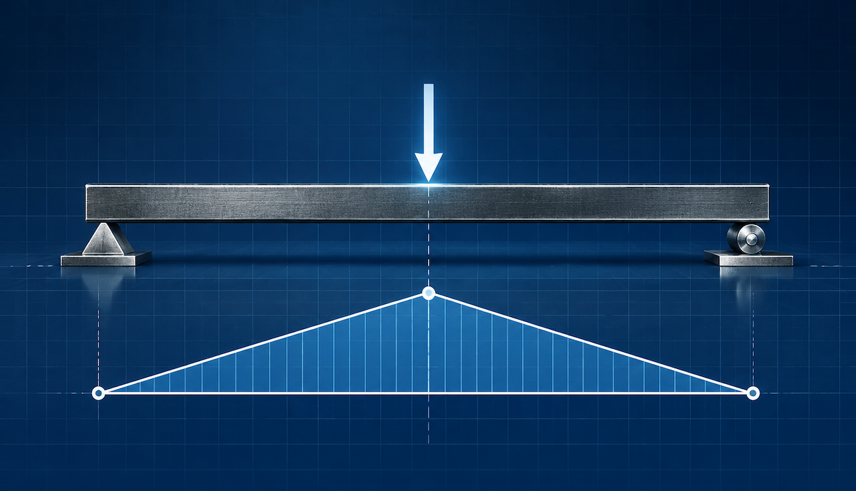
Cut the beam at x = 2.5 m from A and sum the moments on the left-hand side: M(2.5) = RA × 2.5 = 10 × 2.5 = 25 kN·m.
8.4 Steps 3 and 4: Confirm the Location and the Shape
The shear force is +10 kN to the left of the load and −10 kN to the right, so it crosses zero at x = 2.5 m and the moment peak is indeed at midspan, consistent with the formula: Mmax = PL / 4 = 20 × 5 / 4 = 25 kN·m. Now check the shape: the moment diagram is a triangle, zero at both supports, rising linearly to 25 kN·m at midspan and falling linearly back to zero. That is the expected shape for a single point load with no distributed loading.
9. Worked Example 2: Off-Centre Point Load, Peak Away from Midspan
When the load is not at midspan, the symmetric shortcut disappears. The reactions become unequal, and the moment peak shifts towards whichever support is closer to the load.
9.1 Given
Beam type: simply supported, pinned at A and roller at B. Span L = 6 m. Point load P = 30 kN acting 2 m from A, so a = 2 m and b = 4 m.
9.2 Step 1: Reactions
Taking moments about B: RA × 6 = 30 × 4, so RA = 20 kN, and RB = 30 − 20 = 10 kN.
9.3 Step 2: Apply the Formula and Check It
Mmax = Pab / L = (30 × 2 × 4) / 6 = 40 kN·m. The peak sits directly beneath the 30 kN load, 2 m from A, and not at midspan. Checking the moment at x = 2 m from the left end: M(2) = RA × 2 = 20 × 2 = 40 kN·m, which agrees.
9.4 Step 3: Compare with the Midspan Case
The same 30 kN load on a 6 m span produces 40 kN·m when placed off-centre at 2/6 of the span, compared with 30 × 6 / 4 = 45 kN·m if it were at midspan. Load position matters, so the asymmetric case is worth calculating explicitly instead of assuming the worst case is always at midspan.
10. From Maximum Moment to Bending Stress
Calculating Mmax answers what the loading imposes. The next question is whether the section can carry it. For a prismatic member in linear-elastic bending, the bending stress varies linearly across the depth, and the maximum stress occurs at the extreme fibres furthest from the neutral axis:
10.1 The Stress Formula and Three Quantities
σmax = Mmax · c / I = Mmax / W, where σmax is the maximum bending stress in N/mm² or MPa, c is the distance from the neutral axis to the extreme fibre, and W = I / c is the section modulus.
- The second moment of area I depends only on the geometry of the cross-section. Change the material or the load and I does not move.
10.2 Solid Rectangular Section
For a solid rectangular section of width b and height h: I = b · h³ / 12 and c = h / 2, giving W = b · h² / 6.
10.3 Solid Circular Section
For a solid circular section of diameter d: I = π · d⁴ / 64 and c = d / 2.
11. When the Material Enters, and When It Does Not
This deserves a separate emphasis, because it is where beginners misunderstand most: for a statically determinate member, the load-driven M(x) depends only on the loads and the support geometry, not on the material stiffness E. The elastic modulus governs elastic stiffness and therefore deflection and springback, but it does not enter the equilibrium calculation of the moment diagram. In practice, you can finish the moment calculation first and look up the modulus afterwards.
12. First-Yield Moment My — and Why It Is Not a Bending Force
The first-yield moment My marks the capacity limit of the section: the moment at which the extreme fibre just reaches the yield strength σy of the material, My = σy · I / c.
This is not the same calculation as the Mmax from a beam-load analysis. My is a property of the cross-section and the material, while Mmax is a consequence of the applied loads and the support conditions. Comparing them gives the basic elastic design check: under the assumed linear-elastic conditions, if the applied bending moment stays below the first-yield moment, the extreme fibres remain below the yield strength of the material. The comparison on its own does not establish structural safety, because a real design must also account for the applicable safety factors, the load combinations, the section capacity and the relevant engineering standards.
For sheet-metal press-brake work this matters more than anywhere else. The yield moment of a beam section is not a press brake forming capacity. Sheet-metal bending is plastic deformation, and it depends on the tensile strength of the material, the sheet thickness, the die opening, the punch geometry and the bending method. Press-brake tonnage must be calculated with the process-specific bending force method, not with the elastic yield-moment equation. The tonnage formula already published in the site guide is that process formula: P = (650 × S² × L) / (1000 × V), where S is the sheet thickness in mm, L is the bend length in metres and V is the V-die opening in mm, with the constant reflecting mild steel so that other materials need a material factor, roughly ×1.5 for 304 stainless and ×0.5 for aluminium.
13. Four Checks Beyond Bending Stress
A bending stress calculation examines one failure mode. A complete structural assessment usually has to address the following as well, and none of them substitutes for another.
- Deflection: governed by EI, the stiffness. A beam can be overstressed at an acceptable deflection, or the other way round.
- Lateral-torsional buckling: a check that matters for deep, narrow sections in bending, because once the compression edge destabilises, a small bending stress buys nothing.
- Fatigue: where the loads are cyclic, the peak stress amplitude drives the fatigue life, not the static strength alone.
- Code requirements: most applications fall under a design standard such as Eurocode, AISC or ASME, which sets load factors, material factors and check procedures that supersede a simplified elastic calculation.
- And the connections themselves: bolts, welds and anchors often fail before the beam they connect does.
14. The Five Most Common Ways to Get This Wrong
These formulas are powerful precisely because they are fast. That speed becomes a liability as soon as the actual conditions do not match the model. The five categories below are the ones that come up most often in practice, each with its typical symptom and its correction.
| What goes wrong | Typical symptom | How to correct it |
|---|---|---|
| Wrong support or load idealisation | A bolted joint is really semi-rigid, or the beam has long cantilevers, yet it was analysed as simply supported | Model the real boundary condition and run a sensitivity check on the peak location and magnitude |
| Loads missing or double-counted | Self-weight, eccentric connections, reactions from adjacent members and dynamic load factors are routinely left out | Write the load list out item by item and state explicitly what is included and what is not |
| Unit inconsistency | A force in kN with a span in mm gives kN·mm, and the number still looks plausible | State the units at every step and convert explicitly instead of carrying them in your head |
| Applying standard formulas outside their scope | Using Mmax = PL / 4 on a cantilever gives a result four times too low | Build the full M(x) diagram or use verified analysis software, and check where the shear crosses zero |
| FEA and software output | Local axes flipped, units set differently, and results read from the service case instead of the design case | Confirm the local axis orientation and the unit system, then confirm which load case the results belong to |
15. On a Press Brake: When This Line of Thinking Actually Applies
Bringing this line of thinking to a press brake starts with a distinction. The frame of a press brake is not a beam supported at two ends. The ram runs in guides and carries guide reactions and drive thrust, not a simply supported span with a point load on it. Formulas such as Mmax = PL / 4 are therefore not the tool for selecting a press brake.
The structural thinking does have a place on the press brake floor, but with different subjects. The parts that genuinely need a bending moment calculation are the ones being used as loaded members, inside the machine and around it:
- Foundation and anchor bolts: the machine weight, the dynamic loads and the overturning moment all end up travelling through the anchor bolts into the concrete foundation. Foundation capacity and ground settlement decide whether the machine slowly goes out of level in service.
- Cantilevered tables and extended supports: a table added to the machine to lengthen the working length is itself a cantilever beam, and it is loaded by exactly this kind of moment.
- Front supports, rollers and follower supports: these are not decoration. They hand the weight and the centre of gravity of the sheet to the machine, and their load path and stiffness directly affect bending accuracy.
- Tool changes and lifting: the weight of the tooling, the lifting points and the lifting method decide how much moment the beam on your rack actually carries.
16. Structural Formula and Process Formula Are Two Different Ledgers
As for how much force a press brake needs, the answer lives in the process formula, not in the structural one. The simplified air-bending formula published in the site guide is P = (650 × S² × L) / (1000 × V): S is the sheet thickness in mm, L is the bend length in metres and V is the V-die opening in mm, with the constant reflecting mild steel and other materials needing a material factor, roughly ×1.5 for 304 stainless and ×0.5 for aluminium. That and My = σy · I / c are entirely different things: one is the force the process demands, the other is the section limit at which the material starts to yield.
On the machine itself, GWMT offers four press brake platforms. WPA and WPD are CNC platforms, paired with Laimore touchscreen CNC systems and Bosch Rexroth hydraulic systems. WC67K is an NC hydraulic platform using a torsion-axis mechanism with a hydraulic valve group. EP is the all-electric platform, aimed at smaller parts and fast changeover. What separates the four is the drive and the control, not a structural figure for how much bending moment the frame carries. Selection should follow the parts, the material and the production rhythm, and the site guide How to Choose a Press Brake: A Fifteen-Step Path to Acceptance sets that route out in full.
17. Five Questions Worth Asking Any Supplier
A supplier who cannot answer these clearly is a supplier who has not thought about how your operators will actually run the machine, or about whether your shop floor can carry it.
- Under the rated duty, what are the maximum bending moment and the maximum shear force in the frame and the ram, and which calculation supports them?
- What is the specification, the number and the tightening torque of the anchor bolts, and what foundation capacity is required? Is it written into the installation manual?
- What load is permitted on the front tables and the extended supports, and is there a separate calculation and a written statement for it?
- What are the load and stiffness figures for the front supports, the rollers and the follower supports, and how is their effect on bending accuracy characterised?
- What does the site have to provide: floor loading capacity, flatness, the levelling tolerance and a lifting route?
18. Frequently Asked Questions
- Where does the maximum bending moment typically occur?
It depends on the support condition and the load. For a simply supported beam with a central point load it occurs at midspan. For a cantilever it occurs at the fixed support, whether the load is a point load or a uniform load. For an asymmetrically placed point load on a simply supported beam it occurs under the load, not at midspan. The reliable way to locate it is to find where the shear force crosses zero inside the span, and then also check every support location and every load application point.
- How do I find Mmax if I already have the shear force diagram?
Use the relationship dM/dx = V. The bending moment at any position equals the area under the shear force diagram up to that point, and the moment is largest where the shear crosses zero. For a triangular shear force diagram, which is what a simply supported beam with a central load produces, integrate the area of each triangle and add them to obtain the peak at midspan.
- Does the material affect the bending moment calculation?
Not for a statically determinate beam. The load-driven moment M(x) depends only on the applied loads and the support geometry, not on the elastic modulus E and not on the yield strength σy. Material properties enter when you check bending stress with σ = Mc / I or compare against a capacity threshold with My = σyI / c. E governs elastic deflection and springback, not the moment itself.
- What is the difference between bending moment and bending stress?
The bending moment M is an internal force resultant, a couple measured in force times length, such as kN·m. The bending stress σ is derived from M using the geometry of the cross-section, and it is a pressure measured in force per area, such as MPa. The same bending moment produces different stress levels in different sections: a larger, deeper section spreads the same moment over more material, so the peak stress drops.
- When is a hand calculation no longer reliable?
Closed-form formulas apply only to statically determinate members under idealized load arrangements. Beyond that, use verified analysis software or bring in a structural engineer when the beam is continuous over multiple supports, when multiple or partial distributed loads act simultaneously, when the loads or supports are asymmetric in three dimensions, when dynamic, impact or fatigue loads are involved, or when the design must follow a structural code such as Eurocode or AISC and therefore needs load factors, stability checks and detailed connection design.
19. The Whole Path in Six Steps
Calculating the maximum bending moment is straightforward for standard cases, and only when the support condition and the load arrangement are correctly identified first. The formula itself takes seconds to substitute; the judgment about which formula applies is what takes understanding.
- Step one: fix the supports. Pinned, roller, fixed or cantilever; if this one line is wrong, everything after it is wrong.
- Step two: fix the loads. Concentrated, distributed or triangular, and whether self-weight is included — write it down.
- Step three: calculate the reactions and check the magnitude immediately: the reactions must add up to the total load.
- Step four: locate the peak. Evaluate the moment where the shear crosses zero and at every critical boundary, then take the largest absolute value.
- Step five: apply the formula or confirm analytically, then check the shape of the diagram: straight where it should be straight, parabolic where it should be parabolic.
- Step six: carry Mmax into the bending stress check, get the section modulus W from the geometry, and then look at capacity, code requirements and the other checks together.
Technical references
Manufacturer references support process explanations; images illustrate selection topics, not an approved GWMT supply specification.