Contents
- What Is a Press Brake?
- How Does a Press Brake Work?
- Types of Press Brakes
- Press Brake Components
- Press Brake Tooling
- Bending Methods and Process: Air Bending, Bottoming and Coining
- How Press Brake Tonnage Is Calculated
- How to Select a Press Brake
- Press Brake Applications
- Press Brake Maintenance
- Frequently Asked Questions
- Conclusion: One Machine, Five Disciplines
One straight bend, a stamping die forming the part in a single hit, a shear cutting it to size, a roll bending it into a curve — each process has its own boundary. The press brake owns the middle ground: precise straight bends, produced flexibly, with fast tooling changes.
The press brake is also the machine most easily treated as a black box on the shop floor. The operator knows which key to press and how many degrees to bend, but nobody can say whether today's batch came out off-angle because the backgauge did not land, the program was wrong, the tonnage was short, or the tooling itself has worn. This guide is about removing that black box: taking the machine apart and showing you what is inside.
If you are about to buy a press brake, or the one you have keeps giving you trouble, reading this guide in order will give you a complete working understanding. At the end of every chapter I point to the article on this site that covers that one topic in depth, so you can skip it unless you need it.
1. What Is a Press Brake?
A press brake is a machine tool that bends sheet metal and plate along a straight line by pressing an upper tool, the punch, into a lower tool, the die. As the punch drives the material into the die opening, the metal is pushed past its elastic limit and takes on a permanent, controlled bend.
Its defining strength is flexibility: you can put several different bends into the same part on the same machine without rebuilding the setup, which is how one press brake produces everything from a simple 90° flange to a deep box or a complex multi-bend part. That sets it apart from its neighbours on the shop floor — stamping forms a part in one hit with a dedicated die, shearing only cuts material to size, and plate rolling makes curves rather than sharp angles.
A press brake works across mild steel, stainless steel, aluminium, galvanized steel and high-strength steel, and every one of them behaves differently under the punch. That is what makes it interesting, and also what makes it demanding.
The site also has a dedicated piece on terminology: Press Brake vs Brake Press, explaining the technical difference behind the two names.
2. How Does a Press Brake Work?
Every bend follows the same five-step rhythm; only the drive that powers the stroke changes between machines.
2.1 The five steps
Position — the sheet slides in until its edge rests against the backgauge fingers, which decide where the bend line falls. On CNC machines the backgauge moves to the programmed position automatically.
Clamp — the sheet is held between punch and die so it cannot slip once force is applied.
Bend — the ram drives the punch into the V die; the material yields and forms the target angle.
Retract — at the programmed depth the ram returns. The sheet springs back slightly, which the control system compensates for by overbending.
Remove — the finished part comes out and the machine resets.
2.2 What Decides the Quality of the Bend
The quality of the bend is not decided by the drive motor, but by four things together: backgauge accuracy, the control program, the chosen tonnage, and how the punch-and-die geometry is matched to the job.
The backgauge has its own article on this site: Backgauge, covering types, axis configurations, calibration and troubleshooting.
3. Types of Press Brakes
Press brakes are classified by drive type — how the ram is powered. CNC is not a drive type but a control system, so it is treated separately below.
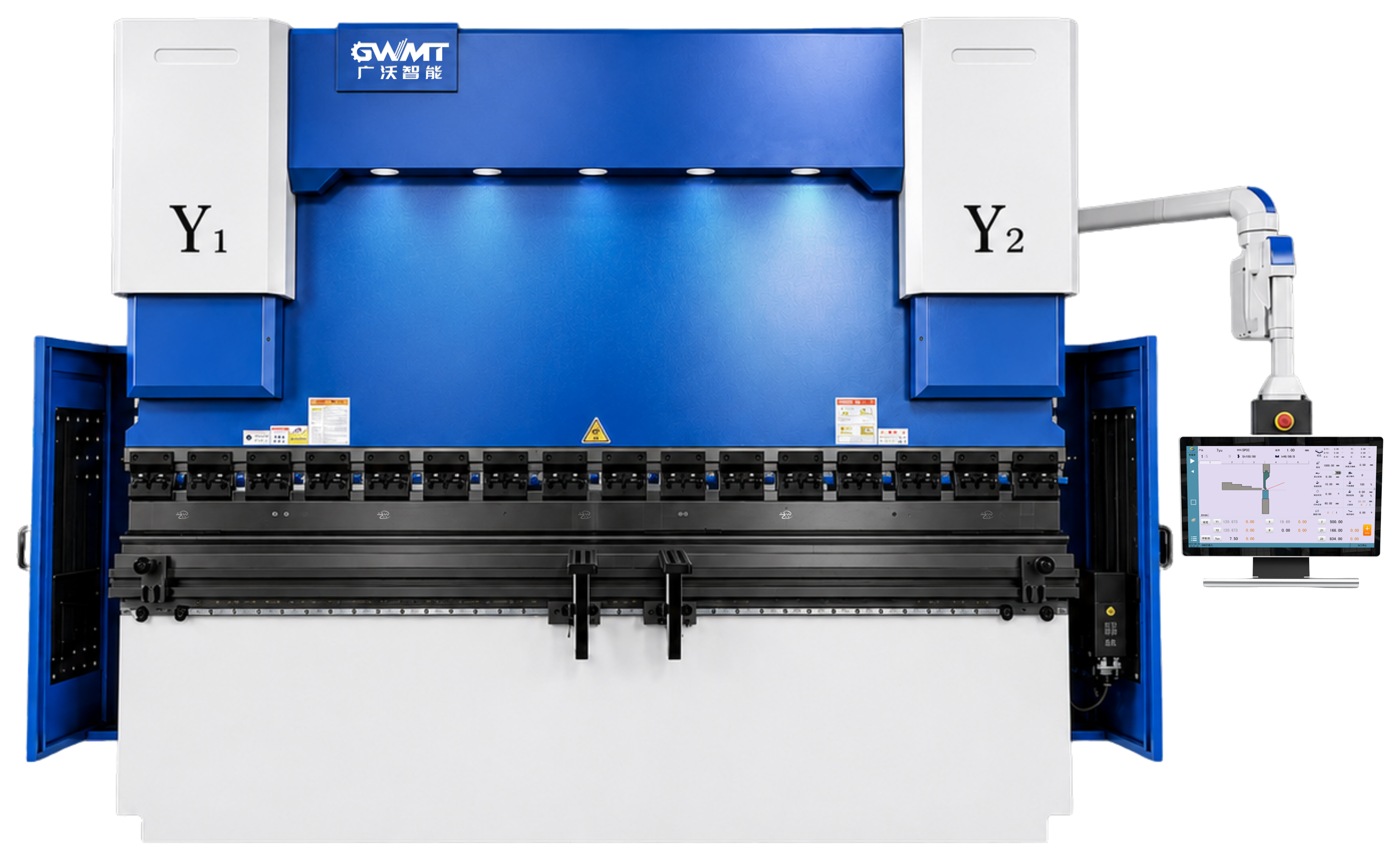
GWMT's own product line covers three of these: the WPA and WPD are hydraulically driven CNC press brakes, the WC67K is a mechanical NC press brake, and the EP series is fully servo-electric. Each has its own detail page.
3.1 1. Hydraulic press brake
Hydraulic cylinders move the ram, making this the mature, general-purpose workhorse of the industry — strong, dependable and comfortable with medium-to-thick plate and higher tonnages. The trade-offs are higher energy use and the routine care a hydraulic system needs.
3.2 2. Electric (servo-electric) press brake
Servo motors drive the ram instead of oil. Electric machines excel on thinner material, precision parts and high-frequency, small-batch work — quieter, cleaner, more energy-efficient and lower-maintenance. Their limit is raw force; the heaviest plate still calls for hydraulic.
3.3 3. Hybrid press brake
A hybrid pairs a hydraulic power source with servo-electric control, keeping hydraulic force while capturing much of the efficiency, quietness and positioning precision of electric drive. It suits shops that want high tonnage without hydraulic-level running costs.
3.4 4. Mechanical press brake
The original design, driven by a flywheel and clutch. Mechanical machines are simple and can deliver high force, but offer poor control over ram speed and lower bending accuracy, so they have largely been displaced by hydraulic and electric machines in modern shops.
3.5 5. CNC press brake (control system)
CNC is not a drive type — it is a control-and-programming layer that sits on top of a hydraulic, electric or hybrid machine. It adds multi-axis backgauge positioning, stored part programs, angle control and the ability to reproduce a complex multi-bend part identically across an entire run. CNC control is now the standard wherever precision and repeatability matter.
4. Press Brake Components
A press brake's accuracy comes from how its core components work together. The main ones are:
- Frame — welded steel plates form the backbone, absorbing every stroke's force and resisting the deformation that would misalign the punch and die.
- Ram (upper beam) — the moving beam that holds the punch and delivers controlled downward force. On CNC machines, independent drive at each end keeps it parallel to the die.
- Punch (upper tool) — contacts the workpiece directly and shapes the bend; different profiles suit different geometries.
- Die (lower tool) — supports the sheet and defines the final bend shape and angle, from a simple V to specialised forms.
- Backgauge — an adjustable stop that locates the sheet relative to the bend line; CNC versions reposition themselves and sequence complex parts automatically.
- Control system — the brain of the machine, coordinating ram position, backgauge location, bending method and angle.
- Hydraulic system — on hydraulic and hybrid machines, the cylinders, pump, valves and oil that generate and control the bending force.
- Supporting parts round out the machine: the bed and workbench hold the die and often a crowning system to counter deflection, the clamping system secures tooling, and optional sheet supports and followers hold up large or heavy blanks during the stroke.
5. Press Brake Tooling
The ceiling on bending quality is usually set by the tooling rather than the machine. The punch-and-die combination decides the inside radius, the flange length and the surface finish, and it also decides how long the tooling lasts before it needs replacing.
Common punch profiles include sharp V, round V and gooseneck, while lower dies come as single V, multi-V four-way, segmented and purpose-built forming dies. Which one applies depends on the shape, the material and the thickness involved.
This topic has two dedicated articles on the site: Choosing a Press Brake V Die Opening covers getting the number right, and Choosing a Press Brake V Die Without Getting It Wrong covers running the process. For the tooling itself, see GWMT's Press Brake Tooling solution.
6. Bending Methods and Process: Air Bending, Bottoming and Coining
Press brake bending is the core process that transforms flat sheet metal into precise angles. The bending method you select directly affects bending force, accuracy, springback and tooling requirements.
The principle in one line: precision always costs something — force, tooling or machine life. Air bending spends the least and suits most work; coining spends the most for the tightest tolerance.
6.1 Air bending
Air bending is the everyday default. The punch presses the sheet only part way into the die, so the angle is set by ram depth rather than die shape. One tool set can produce a wide range of angles just by changing depth, and the force is the lowest of the three — but the angle is sensitive to thickness and springback variation, which modern CNC machines counter with in-process angle measurement.
6.2 Bottoming
Bottoming presses the sheet fully into the die so it conforms to the die walls; the angle is defined by die geometry, giving tighter, more repeatable angles and less springback. The cost is more force and less flexibility — each target angle needs its own die.
6.3 Coining
Coining presses hard enough to imprint the die shape into the metal and effectively eliminate springback, delivering the highest precision — but at very high force that wears tooling and frame far faster, so it is reserved for small, ultra-precise parts.
7. How Press Brake Tonnage Is Calculated
Before choosing a machine or a tool set, you need to estimate the bending force, the tonnage, a job requires.
The site also expands the formula properly: Choosing a Press Brake V Die Opening covers the 16 % radius rule and the 0.77 × V flange rule alongside it.
7.1 The basic formula
A widely used simplified formula for air bending is:
P = (650 × S² × L) / (1000 × V)
The constant reflects mild steel, roughly 450 MPa tensile strength. Multiply by a material factor for others — roughly ×1.5 for 304 stainless and ×0.5 for aluminium.
- P = bending force (tons)
- S = material thickness (mm)
- L = bend length (m)
- V = V-die opening (mm)
7.2 Worked example
Bending 3 mm mild steel, 2 m long, in a 24 mm V-die, where V is about 8 times the thickness:
P = (650 × 3² × 2) / (1000 × 24) ≈ 24 tons for the full 2 m bend. Switch to 304 stainless and it rises to about 36 tons; go to 4 mm thickness and it jumps to roughly 43 tons, showing how sharply force climbs with thickness.
7.3 Using a tonnage chart
Most shops skip the arithmetic and read a tonnage chart: find the row for your material thickness and the column for your V-die opening, and the cell gives tons per metre — multiply by your bend length. The chart already bakes in the thickness-squared relationship and the standard V die, so it is faster and less error-prone for daily work.
Whichever method you use, size the machine with headroom above your typical worst case, but not so much that you pay for capacity you never use.
8. How to Select a Press Brake
There is no single best press brake — only the right one for your parts and production pattern. Work through six questions, then match against the quick guide below.
| Production situation | Match |
|---|---|
| Thin sheet, high speed or small batches | Electric |
| Heavy plate, high tonnage or a wide thickness range | Hydraulic |
| High force with lower running cost | Hybrid |
| Complex parts, tight tolerance and repeatability | CNC on any drive |
| Extra-long or oversized parts | Tandem configuration |
8.1 The six questions
What will you bend? Materials, strength and thickness range set your tonnage baseline.
What is your maximum bending length? Size the bed to your longest part, with margin — a fixed limit you cannot program around.
How much force do you actually need? Estimate tonnage against real parts, not a single worst case.
How complex are your parts? Straight bends versus multi-bend, tapered or irregular parts drive very different backgauge and control needs.
What is your production pattern? High volume of one part, or high-mix low-volume with frequent changeovers — often what tips a decision toward CNC.
How much automation do you need? Multi-axis backgauge, angle measurement, offline programming and robotic loading each add capability and cost.
8.2 Key specifications to consider
When comparing specific machines, check these numbers side by side — they usually tell you more than the feature list on a brochure.
| Spec | Why it matters |
|---|---|
| Tonnage | Maximum bending force; must cover your thickest and longest bend |
| Bending length | Effective working length; must cover your longest part |
| Stroke | Ram travel; affects deep parts and multi-bend clearance |
| Daylight or open height | Vertical space for tooling and tall parts |
| Throat depth | How far in from the frame you can reach; governs deep-box work |
| CNC axes | Backgauge and beam axes; more axes means more complex parts can be automated |
9. Press Brake Applications
Press brakes appear across almost every metal-working sector:
- Automotive — body panels, chassis parts, brackets and reinforcements.
- Aerospace — aircraft skins, airframes and precision assemblies, where tight tolerances make CNC essential.
- Construction and architecture — structural supports, panels, curtain-wall systems and facades.
- Electronics and electrical — cabinets, control enclosures, server racks and switchgear housings, one of the highest-volume applications worldwide.
- HVAC — duct systems and air-handling casings, typically in thin-gauge galvanized sheet.
- Energy — solar mounting frames, wind-turbine parts and transformer housings.
- Appliances — refrigerator cabinets, oven casings and washer frames.
- General and custom fabrication — brackets, frames, channels and one-off custom parts.
- Wherever flat metal needs precise, repeatable straight bends, mass-produced or one-off, the press brake is the tool that does it.
10. Press Brake Maintenance
A structured maintenance routine preserves accuracy, extends machine and tooling life and prevents unplanned downtime.
- Daily inspection — clear metal dust from the bed and die area, and check for visible hydraulic leaks at fittings, hoses and seals.
- Hydraulic maintenance — verify oil level, condition and operating temperature; replace or clean filters at each oil change and change the oil and clean the reservoir at the maker's interval. Replace contaminated oil promptly, as dirty oil damages valves and cylinders quickly.
- Tooling inspection — inspect punch and die for wear, chips or surface damage that would mark the workpiece, and verify tool alignment across the full working length.
- Calibration — run a CNC calibration check at the recommended intervals to confirm positional accuracy has not drifted.
- On safety, a few rules are non-negotiable: confirm tooling is clamped and loaded before every setup, never exceed rated capacity, use appropriate guarding, and plan support for long or heavy parts.
11. Frequently Asked Questions
The six questions below suit item-by-item confirmation with a customer, a colleague or a supplier.
- How accurate is a CNC press brake?
CNC control delivers excellent positioning and repeatability, but the final angle also depends on material consistency, tooling condition, springback and setup. The control system is necessary, not sufficient, on its own.
- How long does a press brake last?
With proper maintenance a quality press brake commonly serves for decades. Tooling also lasts many years, though wear items like hydraulic oil, seals and filters need periodic replacement.
- Can a press brake bend stainless steel?
Yes. Stainless requires more force than mild steel of the same thickness, roughly 1.5 times, and springs back more, so tonnage and springback compensation must be set accordingly.
- What affects press brake accuracy?
Material thickness and strength variation, springback, tool condition and V-die choice, backgauge positioning, bed and ram deflection, which is addressed by crowning, and operator setup all contribute.
- What is the difference between a hydraulic and an electric press brake?
Hydraulic suits thicker plate and higher tonnage; electric suits thinner, precise, high-frequency work with lower energy use and maintenance.
- How do I choose the right V-die opening?
Select it in proportion to material thickness, commonly 6 to 10 times the thickness. It drives the inside radius, the required tonnage and the surface finish.
12. Conclusion: One Machine, Five Disciplines
After these eleven chapters, a press brake should no longer look like a black box that produces an angle when you press a button. It is the convergence of five disciplines: the drive type decides how much force it has, the component accuracy decides how precise it can be, the tooling sets the ceiling on bending quality, the calculation decides whether you will overload it, and maintenance decides whether the other four survive.
If you are about to replace equipment or expand capacity, send us your part drawings. The GWMT engineering team will match the machine, axis configuration, backgauge and tooling together against your material, thickness, bend radius and machine conditions, rather than quoting a price and leaving the rest to you.
Technical references
Manufacturer references support process explanations; images illustrate selection topics, not an approved GWMT supply specification.