Contents
- How Dangerous Is a Press Brake, Really
- The 12 Hazards Behind Most Injuries
- Five Problems We Keep Seeing in Real Shops
- Five Practices Every Shop Should Follow
- Ten Rules to Post Next to the Machine
- Guards and Protection Systems: Where Engineering Takes Over
- Six Safeguarding Options Compared
- Tool Changes, Maintenance and Lockout/Tagout
- Operator Training and Safety Culture
- What OSHA, ANSI, EN and ISO Actually Require
- A Checklist for Every Shift
- Specifying Safety on Your Own Machine
- Four Questions Worth Asking Any Supplier
- Three Principles That Carry Across Every Machine
- Frequently Asked Questions
A press brake can close with enough force to crush bone in a fraction of a second — and unlike most machines, the operator’s hands are usually right next to that closing gap. The job means holding the sheet, aligning the bend line and following the part as it rotates. You cannot simply box the machine in and walk away, because the work itself asks hands to stay close.
That is what makes press brake safety different from general machine safety: the danger zone and the work zone are the same place. Most serious incidents do not happen in a moment when the machine runs wild. They happen in a few seconds when everything looks normal and a hand is simply a few centimetres too close.
This guide covers the 12 hazards behind most press brake injuries, the practices that prevent them, how guards, light curtains and laser protection actually work and where each one stops being enough, what OSHA, ANSI, EN and ISO require, and a checklist your operators can use every shift. Both comparison tables and every standard number are kept as published, ready to look up.
If you are specifying guarding for a new machine right now, several articles on the site go deeper: the complete press brake guide, choosing a V die, and back gauge calibration and troubleshooting. Read the safety boundaries here together with the process figures in those articles and you have the full picture.
1. How Dangerous Is a Press Brake, Really
Start with the answer: press brakes cause some of the most severe injuries in sheet metal fabrication, and most of them are crush injuries or amputations rather than minor cuts. Three things make the machine unforgiving.
First, the force is far beyond human tolerance. Press brakes generate hundreds of kilonewtons of force, enough to cause catastrophic crush injuries in less than a second. There is no such thing as a minor contact injury at the tooling.
Second, slow speed is not safe speed. Reducing the closing speed buys a little more reaction time, but the force is unchanged. A hand caught at slow speed is still a hand caught.
Third, the hazard moves with the job. Box bending, tall flanges, long panels and two-person handling all change where hands go. A guarding setup that works for flat parts may leave gaps on a deep box. The danger zones are not only between punch and die: backgauge fingers and beams move automatically, quickly and quietly, and the machine ends sit beyond the reach of front protection.
Older machines deserve extra scrutiny, but age itself is not the problem. The question is whether the protection still matches how the machine is used today. The cases we see most often are a light curtain moved to clear a fixture, a control retrofit done without recalculating the safety distance, or guarding removed for one job and never refitted. A safeguard that is present but wrongly positioned is more dangerous than no safeguard at all, because everyone assumes they are protected.
2. The 12 Hazards Behind Most Injuries
These are the hazards that account for the majority of press brake incidents. Read them as a checklist: if you cannot name the control for each one on your machine, that is your gap.
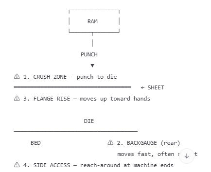
- 1. Punch-to-die crush zone. The space where the material forms. Contact here typically means fracture or amputation.
- 2. Rising flange. As the bend forms, the flange rotates upward toward the operator’s hands, arms and face. Tall flanges and box parts create a moving hazard that did not exist when the cycle started.
- 3. Part ejection. An unsupported or badly located blank can kick out of the tooling under load and strike the operator.
- 4. Backgauge movement. Backgauge fingers and beams move automatically, quickly and quietly. Reaching behind the bend line to clear a slug or reposition a part is a classic trapping scenario.
- 5. Reach-around at machine ends. Front protection does not protect the sides. Operators reaching around the guarding to access the ends of the bed is a well-known weak point.
- 6. Falling tooling. Punch and die segments are dense and heavy. Dropped tooling causes foot and hand injuries during handling, transport and storage.
- 7. Sharp edges and burrs. Laser-cut and sheared blanks cause lacerations during loading, unloading and stacking — often the most frequent injury type by count.
- 8. Accidental foot pedal actuation. A pedal sitting in a walkway, an unguarded pedal, or a trailing cable can start a cycle nobody intended.
- 9. Unexpected ram motion. Caused by stored hydraulic energy, a control fault, a wrong program, or a second person starting the machine while the first is inside the danger zone.
- 10. Bypassed or defeated safeguards. Not a machine hazard — a decision. It is also one of the most common findings in accident investigations.
- 11. Slips, trips and falls. Hydraulic oil, coolant, offcuts and cables are dangerous anywhere, but far worse when the person falling is carrying a sharp 20 kg blank next to a machine.
- 12. Noise, fatigue and ergonomic strain. Lifting and positioning sheet all shift loads the back, shoulders and wrists. Fatigue degrades exactly the attention that hazard avoidance depends on.
| Hazard | Typical consequence | Primary control |
|---|---|---|
| Punch-to-die crush zone | Amputation, fracture | Verified safeguarding device, no bypass |
| Rising flange / ejection | Impact, laceration | Supports, fixtures, correct setup |
| Backgauge movement | Trapped hands | Rear access control, awareness barriers |
| Reach-around at ends | Crush injury | Side guarding, extended protection |
| Falling tooling | Crush, foot injury | Lifting aids, tooling racks |
| Accidental pedal actuation | Unintended cycle | Guarded stable pedal, cable routing |
| Unexpected ram motion | Crush during service | Lockout/tagout, energy isolation |
| Slips and trips | Falls into machine | Spill control, housekeeping |
3. Five Problems We Keep Seeing in Real Shops
Work with sheet metal shops long enough and you notice that most press brake safety problems do not come from machine design. They come from what happens after installation: improper operation, outdated protection and undocumented changes made on the shop floor. These are the five situations that come up most often during commissioning, service visits and upgrades.
- “The light curtain kept stopping the job, so we adjusted it.” Running a deep box, an operator finds the curtain interrupting mid-cycle, so blanking is widened or the device is repositioned to keep production moving. The bend now runs; the protection no longer covers the hazard. What should happen instead: box bending and tall flanges are exactly what laser AOPD protection was designed for, and changing a protective device’s configuration is an engineering change, not an operator adjustment.
- The foot pedal has migrated. Pedals get moved for comfort and stay wherever they land: in walkways, on cable runs, or positioned so the operator works in a twisted stance with poor sightlines to the bend line. What should happen instead: a defined pedal position, cable routed clear of traffic, and guarding against unintended actuation. If the operator has to twist to reach the bend line, the layout is wrong.
- An old machine was upgraded but never revalidated. Retrofitted CNC controls, replaced valves and new backgauge systems get installed on machines whose safety distance was calculated years earlier, for different stopping performance. Stopping time changes as valves, brakes and controls wear or get replaced; if it changed and the safety distance did not, the protection is now theoretical. What should happen instead: measure stopping performance and recalculate the safety distance after any change to the control, drive or braking system.
- Wrong or worn tooling makes bends unstable. Mismatched tooling, worn V-dies and uneven clamping cause parts to slip under load. The operator responds by holding the part more firmly, which means holding it closer to the tooling. Tooling condition is a safety issue, not only a quality issue.
- Nobody can say who is in charge during two-person bends. On long parts, two operators regularly work the same machine with no agreed command protocol. Both assume the other is watching, and the stroke starts before one of them is clear. What should happen instead: one lead operator, one voice, one fixed phrase before every stroke.
4. Five Practices Every Shop Should Follow
These are the practices that prevent the hazards in the previous section. They cost nothing except discipline.
- 1. Run the same pre-start check every shift, in the same order so a skipped step is obvious: emergency stops, light curtain, laser protection and interlocks correctly positioned and tested, a stable guarded pedal with its cable clear of walkways, no hydraulic leaks, damaged hoses or exposed wiring, ram and backgauge homing correctly, tooling clean, undamaged and seated, and the floor and bed clear of oil and offcuts. The rule that matters most: if a safety device fails its check, the machine stops working — it does not run “carefully until Friday”. Repeatedly resetting a fault to keep production going is the clearest early warning sign of a serious incident.
- 2. Never put hands between punch and die. No exceptions, no modes, no speeds. Use front sheet supports for large panels, magnetic grippers or tongs for small blanks, and keep hands on the part edges well outside the tooling line. Marking a “no-hands” line on the bed helps as a visual reminder — but it is a reminder, not a safeguard.
- 3. Treat setup as the high-risk activity it is. A significant share of press brake injuries happen during setup, not production. Clean the tooling and clamping surfaces, inspect for cracks and wear, seat tooling fully, clamp to the manufacturer’s specification, verify punch-to-die alignment and run a slow trial stroke before production speed. Never use damaged, deformed or mismatched tooling.
- 4. Select PPE by task, not by habit. Baseline for a bending cell: safety eyewear, toe-protected footwear, hearing protection where exposure warrants it, and close-fitting clothing with no rings, watches or loose sleeves. On gloves, read this carefully: cut-resistant gloves are often essential for handling sharp blanks, but where hands work near the tooling they can create snagging risk and a false sense of protection. Decide by risk assessment and the machine manufacturer’s instructions, write the rule into the work instruction, and do not leave it to individual judgement.
- 5. Keep the area around the machine clear. Clean spills immediately, store tooling in racks rather than on the bed, secure pedal cables out of walkways, mark operator positions and no-entry zones, and keep bright, glare-free lighting over the bend line.
5. Ten Rules to Post Next to the Machine
If you post one thing next to the machine, post these ten.
- 01. Do not start work until the safety check is complete. A failed check means the machine is out of service.
- 02. Hands never enter the point of operation. Not in setup, not at slow speed, not “just for a second”.
- 03. Never bypass, blank out or reposition a safeguard. If the device is interfering with the job, the setup is wrong — escalate it.
- 04. One operator controls the pedal. In team work, one lead operator initiates and calls the stroke.
- 05. Confirm before every stroke. Use a fixed phrase: “hands clear — bending”. Never assume.
- 06. Support the part properly. Large panels get sheet supports; small parts get grippers or fixtures.
- 07. Stop on anything abnormal. Unusual noise, erratic ram motion, a fault code, a slow response — stop and report.
- 08. Lock out before any tooling or maintenance work. Switching off is not isolation.
- 09. Never remove another person’s lock or tag. This is the most serious breach in the shop.
- 10. Report near misses. A near miss is free information about how the next injury would happen.
6. Guards and Protection Systems: Where Engineering Takes Over
This is where engineering does the work that discipline alone cannot. The goal is either to prevent access to the hazard, or to detect access and stop the motion in time.
One rule applies to all of them: whatever device you choose, it must be integrated into a safety-related control system, tested at defined intervals, and protected against bypass by both design and policy. A safety device wired through an ordinary control relay is not a safety function — it is a convenience feature that looks like one.
6.1 Barrier Guards
Physical barriers are the simplest and most reliable protection — where they fit. Fixed guards suit the rear and sides where routine access is not needed. Interlocked movable guards allow access for setup while preventing motion when open.
Their limitation is the front of the machine, where the operator has to hold and follow the part. Guarding the rear and ends while leaving the front unaddressed is a common and serious gap.
6.2 Light Curtain Protection
A light curtain is the most common safety device installed on press brakes. It creates an invisible protection zone in front of the tooling area. If an operator’s hand enters this zone during operation, the system sends a stop signal before the punch reaches the material.
It only works correctly when four conditions hold: it is installed at the correct safety distance; the machine’s actual stopping time has been measured, not assumed; stopping performance is monitored, because it degrades as valves and brakes wear; and operators do not bypass, disable or widen the blanking to make a job run.
One point worth understanding: to let a flange rise through the sensing field without stopping the cycle, the curtain uses muting or blanking. These are engineered functions with validated limits, not settings to be adjusted on the shop floor when a part does not clear. Casual field adjustment of blanking is one of the most common routes to an unprotected hazard we encounter.
6.3 Laser Protection (AOPD)
Laser protection — technically an active optoelectronic protective device, or AOPD — works differently. Instead of guarding the whole approach area, it monitors a narrow field directly below the punch tip and travels down with the ram. That means the operator can hold the part close to the tooling and still be protected.
Best suited to box bending and parts with tall side flanges, work requiring the operator to support the part near the tooling, and applications where a vertical light curtain would need extensive blanking. It is not a universal answer: suitability depends on tooling geometry, part shape and control integration. Compound tools and unusual die setups may still need a light curtain, a barrier, or a combination of both on the same machine.
Note also that “AOPD”, “laser scanner” and “optical protective device” are not interchangeable terms. When specifying, name the actual device type and its certified performance level.
6.4 Two-Hand Control
Two-hand control guarantees both hands are clear when the stroke starts. It suits fixtured parts that need no hand support during forming.
To be effective it must include anti-tie-down, synchronous actuation and control-circuit monitoring — otherwise it can be defeated with a strap or an elbow.
7. Six Safeguarding Options Compared
Here is the choice compressed into one table, to compare against when the decision is actually being made. Every row is a real technical difference rather than a sales argument.
| Safety Device | Best For | Advantage | Limitation |
|---|---|---|---|
| Light curtain | Standard open bending | Flexible, open access, no physical barrier | Requires correct safety distance; blanking limits |
| Laser AOPD | Box bending, tall flanges | Close-proximity protection, operator can support part | Tooling geometry restrictions; not suited to all die setups |
| Two-hand control | Fixtured parts, no hand support | Physically prevents hand entry at initiation | Limited applications; must resist defeat |
| Fixed barrier guard | Rear and side access | Simple, highly reliable, low maintenance | Blocks access needed for setup and part handling |
| Interlocked movable guard | Setup and maintenance access | Combines access with protection | Interlock must be integrated in a verified safety circuit |
| Combined curtain + AOPD | Mixed job shops | Covers die setups neither device handles alone | Higher cost, more commissioning and validation |
8. Tool Changes, Maintenance and Lockout/Tagout
Tool changes are where normal safeguarding protects you least, because the work requires being inside the hazard zone with guards moved. Punch and die segments are heavy and easily dropped, hands go directly into the pinch zone during seating and clamping, and critically, stored energy remains after the machine is switched off: hydraulic pressure and the weight of the ram itself do not disappear with the switch.
The following is the general principle. It does not replace your site-specific written procedure, which must be built from the manufacturer’s instructions and your own risk assessment. OSHA’s requirements for controlling hazardous energy are set out in 29 CFR 1910.147.
Use tooling carts, magnetic or mechanical lifters and hoists rated for the load. Never place any part of your body under a suspended load. Return removed tooling to labelled racks immediately. Inspect clamps and bolts for wear before reinstallation, and tighten to the specified torque and sequence — uneven clamping is a shift risk under load. Preventive maintenance and safety are closely linked: a machine with worn valves and slow response is both less accurate and less safe.
Never remove another person’s lock. There is no situation on a shop floor where this is acceptable.
- 1. Notify affected personnel and shut down using the normal stopping procedure.
- 2. Isolate all energy sources — electrical, hydraulic, pneumatic, gravitational.
- 3. Release or restrain stored energy, including residual hydraulic pressure and ram weight.
- 4. Apply individual locks and tags — every person applies their own.
- 5. Verify isolation by attempting a normal start and confirming no motion is possible.
- 6. Use mechanical supports and lifting aids for the work.
- 7. On completion: tools removed, guards refitted, personnel clear, then locks removed in order.
9. Operator Training and Safety Culture
Equipment sets the ceiling for how safe an operation can be. Training and culture decide how close you get to it.
Competent operators must understand machine construction and hazard zones; normal operation, setup and abnormal-condition response; tooling installation and inspection; how the installed safeguarding works and what it does not protect against; how to test safety devices using the manufacturer’s method; foot control discipline and multi-operator protocol; the boundary between operator tasks and maintenance tasks requiring isolation; and how to report faults and near misses. An operator who cannot explain the limits of their own safeguarding has not been fully trained.
Retrain after a new machine, control system or safety upgrade; after new tooling, part geometry or process; after any incident or significant near miss; after a period away from the equipment; and whenever monitoring shows procedures drifting.
- Records that matter: machine-specific work instructions, training and authorisation records, daily check records, safety device test records, maintenance and fault logs, and incident and corrective-action records.
- And one cultural point: if reporting a near miss creates blame, near misses stop being reported. You lose your cheapest early warning signal at exactly the moment you need it.
10. What OSHA, ANSI, EN and ISO Actually Require
Before the numbers, one boundary worth stating: requirements depend on your jurisdiction, machine configuration and application, and you should always work from the current published version. What follows sets out the role and the number of each framework, not a compliance verdict on any particular machine.
Compliance note: always consult current applicable regulations, the machine manufacturer’s instructions and a qualified safety professional before commissioning, modifying or retrofitting a press brake. The standards and numbers listed here are technical references only; they do not state that any GWMT model holds the certifications or conformity conclusions mentioned above. Configuration and compliance responsibilities must be confirmed item by item during project review.
10.1 United States: OSHA and ANSI
OSHA addresses machine guarding for general industry under 29 CFR 1910 Subpart O, with the general machine guarding requirement in 29 CFR 1910.212. Machine guarding remains one of OSHA’s most frequently cited areas, and guarding citations are commonly classified as serious.
ANSI B11.3 is the U.S. standard written specifically for power press brakes. It covers risk assessment, point-of-operation hazards, and the selection of guards and protective devices, including close-proximity AOPD safeguarding. The current edition is ANSI B11.3-2022, which supersedes the 2012 version. Verify the edition you are working to.
ANSI B11.19 sets performance requirements for the safeguarding devices themselves — B11.3 tells you what to select, B11.19 tells you what it must achieve. ANSI B11.TR3 provides risk assessment guidance. Risk assessment is what connects a generic standard to your specific machine, and should be performed at commissioning, after any modification or retrofit, after a process change, following an incident, and at periodic intervals.
10.2 Europe: Machinery Legislation, EN 12622 and ISO 13849-1
EN 12622 is the European Type-C standard for hydraulic press brakes, currently published as EN 12622:2009+A1:2013. Note that press safety standards are undergoing revision toward the EN ISO 16092 series, so confirm the applicable version for your market and machine.
ISO 13849-1 provides the framework for designing and assessing safety-related parts of control systems, including performance levels based on severity of harm, frequency of exposure, and possibility of avoidance. The current edition is ISO 13849-1:2023.
On CE marking, one clarification is worth making: CE is not a third-party certification badge applied to an individual safety device. It is part of the manufacturer’s conformity assessment and declaration for the machine against applicable EU legislation. Buying a machine with advanced safety features does not by itself make an installation compliant — installation, integration, risk assessment, procedures, training and maintenance all contribute.
11. A Checklist for Every Shift
Print this and keep it at the machine.
11.1 Before Operation
- Emergency stops present, undamaged, functional.
- Light curtain or laser protection positioned, unobstructed, tested per manufacturer’s method.
- Foot pedal stable and guarded; cable clear of walkways.
- No hydraulic leaks, damaged hoses or exposed wiring.
- Ram and backgauge home correctly with normal motion.
- Tooling clean, undamaged, correctly seated and clamped.
- Bed and floor clear of oil, offcuts and obstructions.
- Task-appropriate PPE worn; no loose clothing or jewellery.
11.2 During Operation
- Hands stay outside the point of operation at all times.
- Supports, grippers or fixtures used for large, heavy or small parts.
- One designated lead operator controls initiation in team work.
- Stop immediately on abnormal noise, motion, warning or fault.
- No safeguard bypassed, blanked or repositioned to keep production running.
11.3 During Tool Change and Maintenance
- Site-specific lockout/tagout applied.
- All hazardous energy isolated, released or restrained, and verified.
- Mechanical supports and lifting aids used.
- No body part under an unsupported load.
- Clamps, bolts and tooling inspected and torqued before restart.
- Guards refitted and personnel clear before locks removed.
12. Specifying Safety on Your Own Machine
If you are buying or replacing a machine, safety is not a line item you add at the end. It is a configuration decision that depends on the work you actually do.
For the GWMT range specifically, WPA and WPD are CNC platforms with configurable axes, suited to complex profiles and varied production; WC67K is an NC-controlled hydraulic platform for straightforward bending and repeat jobs; EP is a compact all-electric platform built for fast response and quick changeover on smaller precision parts. These describe platform types, not safety configurations. Point-of-operation protection type, safety distance, rear access control and the compliance target for your market all have to be written down at quotation stage alongside tonnage and bed length, from your own part list and local regulations. Retrofitting protection later typically costs several times more than specifying it correctly.
A separate page on the site collects reference material on laser protective devices: sensing-zone diagrams, transmitter and receiver units, and mounting positions, all as selection references. Those drawings and devices are third-party references, not a confirmed GWMT supply list or performance commitment. Any muting, blanking or mode setting must be based on approved device documentation and a qualified machine-safety process, never installed or adjusted from a diagram alone.
The boundary worth stating plainly: the standard numbers, protective device types and checks in this article are general technical references. They are not a GWMT commitment to any certification, conformity conclusion, response time or scope of supply. Installation, integration, risk assessment, procedures, training and maintenance together determine whether an installation is compliant. Work from current applicable regulations, the machine manufacturer’s instructions and a qualified safety professional.
- Your real application mix: flat panels and deep boxes need different protection. Tell the supplier what share of your parts have tall flanges before quotation, not after installation.
- Point-of-operation protection type: light curtain, laser AOPD, or both. This is the decision that most affects daily productivity — get it wrong and operators will be tempted to work around it.
- Stopping performance and safety distance: ask for the measured stopping time, how the safety distance was derived, and how it will be re-verified over the machine’s life.
- Rear and side protection: confirm how reach-around and rear access are addressed, not just the front.
- Tooling and clamping system: quick-change clamping with tool-seating detection reduces exposure during one of the highest-risk activities on the machine.
- Compliance target: CE-related legislation for the European market, OSHA and ANSI B11.3 for U.S. operations — confirm this at quotation stage, because retrofitting protection later costs several times more than specifying it correctly.
13. Four Questions Worth Asking Any Supplier
A supplier who cannot answer these clearly is a supplier who has not thought about how your operators will actually run the machine.
- What stopping time was measured on this machine, and at what safety distance is the protective device set?
- Which of my part geometries will the standard protection handle without blanking adjustment?
- What safety validation documentation is supplied with the machine?
- What is required to revalidate safety after a control or tooling change?
14. Three Principles That Carry Across Every Machine
The shops that perform best on safety usually perform well on uptime and quality too, and it is the same cause in both cases: the machine is correctly configured for the work, tooling is in good condition, procedures are followed, and problems get reported instead of worked around.
- Engineering controls do the heavy lifting. Guards, light curtains, laser protection and interlocks provide the primary protection; behaviour and PPE manage what is left over.
- Protection must match the application. The right setup for flat panels may be inadequate for deep boxes. That judgement comes from a risk assessment of your machine, your parts and your people.
- Verification never stops. Stopping performance changes, devices drift, procedures erode and people move on. Testing, auditing and retraining are what keep a safety system real rather than nominal.
15. Frequently Asked Questions
- Is bending at slow speed safe?
No. Reducing the closing speed only buys a little more reaction time; the force is unchanged. A hand caught at slow speed is still a hand caught. The point of operation always needs a verified safeguarding device, not a slower speed setting.
- The light curtain keeps stopping the job — can we just widen the blanking?
Not as an operator adjustment. Muting and blanking are engineered functions with validated limits; changing the configuration changes what the protection covers. Deep boxes and tall flanges are exactly what laser AOPD protection was designed for. A configuration change is an engineering change: escalate it and revalidate.
- Does buying a machine with advanced safety features make us compliant?
No. CE, for example, is part of the manufacturer’s conformity assessment and declaration for the machine against applicable EU legislation, not a badge on an individual safety device. Installation, integration, risk assessment, procedures, training and maintenance all contribute. Work from current regulations, the manufacturer’s instructions and a qualified safety professional.
Technical references
Manufacturer references support process explanations; images illustrate selection topics, not an approved GWMT supply specification.