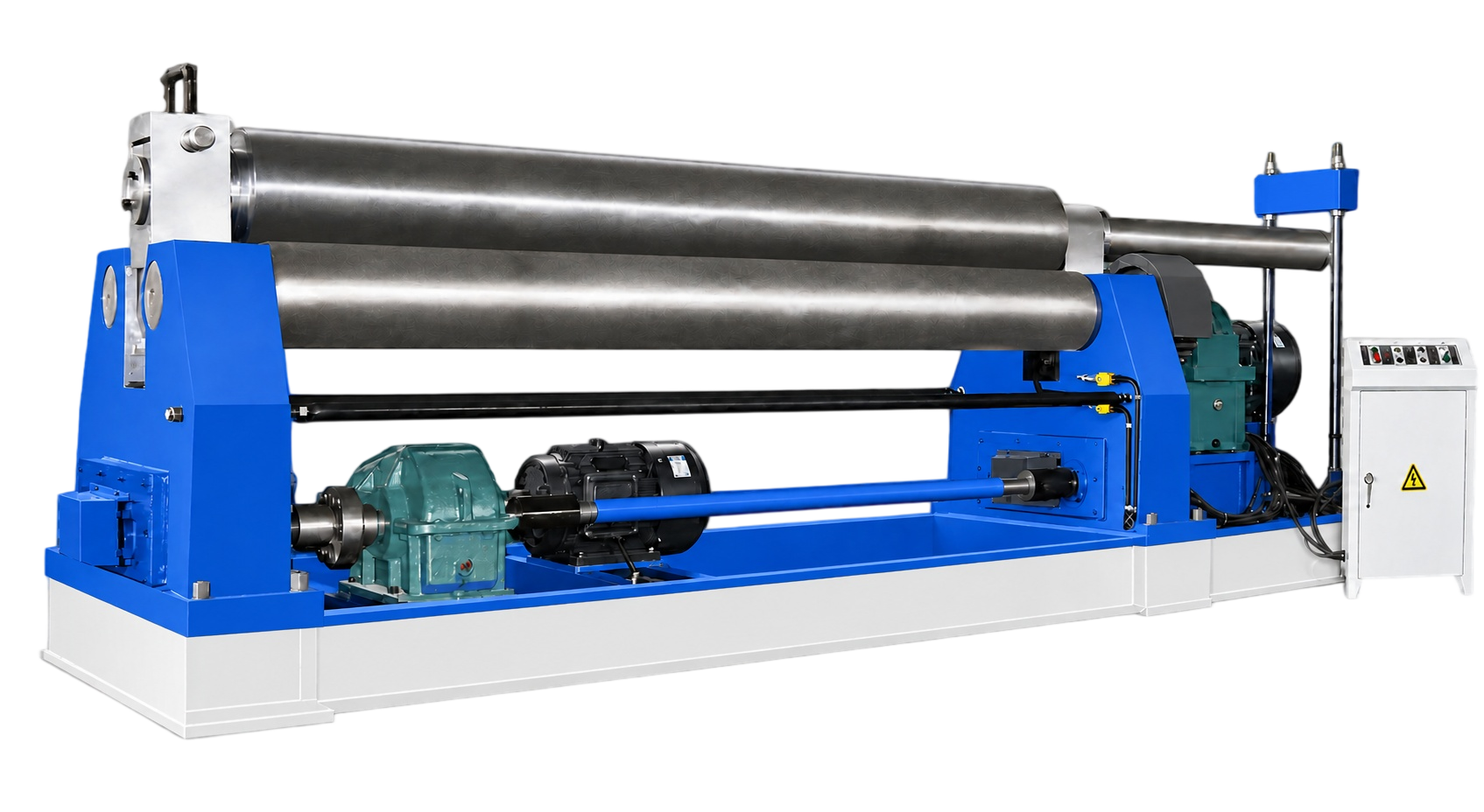
Symmetric three-roll layout
The upper roll moves vertically in the centre line between two lower rolls, creating a clear and repeatable mechanical rolling arrangement.
structureA practical three-roll platform for economical cylindrical and curved plate forming, configured around the sheet schedule, required diameter, working length, and handling method.
PRODUCT OVERVIEW
The W11 symmetric arrangement positions the upper roll centrally above two driven lower rolls. It is a robust starting platform for regular cylinder and arc work where the process, plate range, and finishing expectations are clearly defined.
CONFIGURATION POINTS
The upper roll moves vertically in the centre line between two lower rolls, creating a clear and repeatable mechanical rolling arrangement.
structureScrew, worm, and geared adjustment is selected around the rolling load, required radius, and operator working method.
positioningThe lower rolls provide traction for controlled plate travel. Their drive arrangement is reviewed against material grade, thickness, and cycle demand.
driveRoll diameter, working face, and surface condition are considered with the target cylinder, curve, cone requirement, and acceptable marking risk.
toolingA symmetric three-roll process may require a planned approach for plate ends. The acceptable straight length and supporting method are confirmed early.
workflowFeeding, side support, discharge space, lifting method, and operator access are defined around the sheet format and finished workpiece weight.
safetyDesigned to deliver reliable performance across a range of fabrication requirements.
| Model | Max thickness of coiled plate mm | Max width of coiled plate mm | Yield limit of sheet metal MPa | Diameter of top shaft mm | Motor power kW |
|---|---|---|---|---|---|
| W11-4×1500 | 4 | 1500 | 245 | 150 | 3 |
| W11-6×1500 | 6 | 1500 | 245 | 160 | 4 |
| W11-6×2000 | 6 | 2000 | 245 | 185 | 5.5 |
| W11-6×3200 | 6 | 3200 | 245 | 240 | 7.5 |
| W11-8×2000 | 8 | 2000 | 245 | 230 | 5.5 |
| W11-8×2500 | 8 | 2500 | 245 | 230 | 7.5 |
| W11-12×2000 | 12 | 2000 | 245 | 240 | 7.5 |
| W11-12×2500 | 12 | 2500 | 245 | 260 | 7.5 |
| W11-12×3000 | 12 | 3000 | 245 | 280 | 11 |
| W11-16×2000 | 16 | 2000 | 245 | 260 | 7.5 |
| W11-16×2500 | 16 | 2500 | 245 | 300 | 11 |
| W11-16×3200 | 16 | 3200 | 245 | 340 | 15 |
| W11-20×2000 | 20 | 2000 | 245 | 280 | 11 |
| W11-20×2500 | 20 | 2500 | 245 | 340 | 15 |
| W11-25×2000 | 25 | 2000 | 245 | 330 | 15 |
| W11-25×2500 | 25 | 2500 | 245 | 380 | 22 |
| W11-30×2500 | 30 | 2500 | 245 | 400 | 30 |
| W11-30×3000 | 30 | 3000 | 245 | 450 | 37 |
Parameters are subject to continuous product improvement. Final technical agreement governs supply.
TAILORED TECHNICAL PROPOSAL
Share drawings, materials, target output, and current process constraints. An engineer can use them to prepare the next conversation.