
Contents
- The V Opening Chart: Five Parameters at a Glance
- What Is a V Die Opening?
- How to Calculate It: The Rule of 8
- Recommended Openings by Material
- V Opening and Bend Radius: the 16 % Rule
- How the V Opening Affects Tonnage
- Minimum Flange Length Based on the V Opening
- Choosing the Right V Opening, Step by Step
- Four Mistakes When Selecting a V Opening
- Frequently Asked Questions About V Die Openings
- Conclusion: an Opening Is an Engineering Decision
The one number in the bending shop that gets decided by feel is the width of the V groove. A press operator glances at the drawing, calls out a slot width, and the job runs on. That single number is quietly carrying three consequences: the inside radius of the part, the tonnage the press brake has to exert, and how short the flange is allowed to be. Choose the opening correctly and you get accurate angles, a predictable radius and long tooling life. Choose it badly and you have invited cracked parts, chipped dies, overloaded machines and scrap.
This guide is not going to hand you a table to copy and stop there. It tries to answer the deeper question: why the Rule of 8 works as well as it does, when you must depart from it, and which numbers you have to re-check once you do. Work through the logic and you can reason your way through a new material, a new thickness or a different machine on your own.
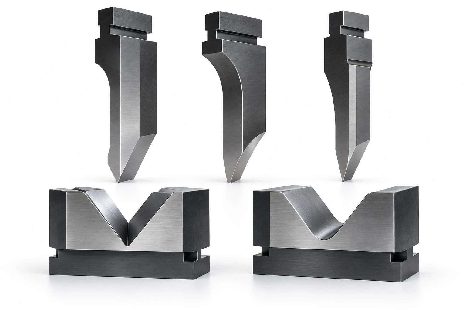
1. The V Opening Chart: Five Parameters at a Glance
The table below covers the most common case: mild steel at roughly 450 N/mm² tensile strength, bent to 90° in air bending. It links the five numbers that pull against each other — material thickness t, V opening V, inside bend radius ir, minimum flange length b and required tonnage per metre F. Every opening in it follows the Rule of 8, V ≈ 8 × t.
These are widely accepted industry reference values. Actual results vary slightly with material batch, tooling condition and machine calibration; the openings listed are the ideal recommendations derived from the Rule of 8.
- Step one: find your material thickness t in the first column.
- Step two: read off the recommended V opening — the safest and most efficient starting point.
- Step three: check the consequences — the inside radius, the minimum flange and the tonnage are now predictable before you ever load a sheet.
| Material thickness (t, mm) | V die opening (V, mm) | Inside bend radius (ir, mm) | Minimum flange length (b, mm) | Required tonnage per meter (F, t/m) |
|---|---|---|---|---|
| 1.0 | 8 | ≈ 1.3 | > 5.5 | ≈ 8 |
| 1.5 | 12 | ≈ 2.0 | > 8.5 | ≈ 10 |
| 2.0 | 16 | ≈ 2.6 | > 11.0 | ≈ 12 |
| 2.5 | 20 | ≈ 3.3 | > 14.0 | ≈ 14 |
| 3.0 | 25 | ≈ 4.0 | > 17.5 | ≈ 16 |
| 4.0 | 32 | ≈ 5.0 | > 22.0 | ≈ 22 |
| 5.0 | 40 | ≈ 6.5 | > 28.0 | ≈ 27 |
| 6.0 | 50 | ≈ 8.0 | > 35.0 | ≈ 32 |
| 8.0 | 63 | ≈ 10.0 | > 45.0 | ≈ 45 |
| 10.0 | 80 | ≈ 13.0 | > 55.0 | ≈ 56 |
2. What Is a V Die Opening?
The V die opening, also called the die width or simply V, is the distance across the top of the V-shaped groove in the lower die. In air bending it is the single most critical dimension, because it is not merely a support platform: it directly defines the floating inside bend radius of the part.
In air bending the sheet touches only three points: the punch tip and the two shoulders of the V die. The metal floats in the opening, and the inside radius forms naturally across those two shoulders. That is why, in modern air bending, the punch tip radius is largely irrelevant — the V opening is the real programmer of your bend.
Three features of the die work together, and understanding them tells you what to specify when you order tooling.
- V opening, or die width: governs the inside radius and the required tonnage.
- Die angle: usually slightly sharper than the target, 88° or 85° for example, to allow over-bending and control springback.
- Shoulder radius: the smooth transition into the groove. A larger, better-polished shoulder reduces die marks on stainless and aluminium, but it needs a longer minimum flange.
3. How to Calculate It: The Rule of 8
The industry golden standard is the Rule of 8: for 90° air bending in mild steel, the ideal V opening is about eight times the material thickness.
3.1 The formula
V die opening = 8 × material thickness
3.2 A worked example
For a 2 mm mild steel sheet: 2 mm × 8 = 16 mm, so you use a V16 die.
That ratio strikes an almost magical balance between bending force, angle accuracy and springback control. It naturally produces an inside radius roughly equal to the material thickness, about one sixth of the V opening, which keeps bend allowance calculations simple and repeatable.
3.3 When to Vary the Multiplier
The 8× rule is tuned for mid-range mild steel. Adjust the multiplier by thickness and material.
The science behind it: when V = 8t for mild steel, the neutral-axis position, the K-factor, delivers an inside radius roughly equal to the material thickness. It is backed by both empirical validation and solid engineering, but it is a starting point, not an unbreakable law.
- Thin gauge, under 3 mm: 6× – 8× t
- Mid-range mild steel: 8× t
- Heavy plate, over 10 mm: 10× – 12× t
4. Recommended Openings by Material
The Rule of 8 is not one-size-fits-all. Different materials have different tensile strengths and ductility, so the multiplier has to change. Use the table below as your conversion reference, then read the material-specific notes.
| Material | Tensile strength (UTS) | V-opening rule | Tonnage factor vs. mild steel | Inside radius (% of V) |
|---|---|---|---|---|
| Mild steel, baseline | ≈ 450 N/mm² | 8 × t | 1.0× | 16–17% |
| Stainless steel (304) | ≈ 600 N/mm² | 10–12 × t | 1.4–1.5× | 20–22% |
| Aluminium (5052, soft) | ≈ 230 N/mm² | 5–6 × t | 0.5–0.6× | 13–15% |
| Aluminium (6061-T6, hard) | Higher, low ductility | 10–12 × t | ≈ 1.0× | 13–15% |
| High-strength steel | > 800 N/mm² | 12–20 × t | 2.0–3.0× | Varies |
4.1 Mild steel
Apply the Rule of 8, V = 8t. It is the safest and most efficient default and yields an inside radius roughly equal to the material thickness. For example 3 mm mild steel leads to V24, with V25 shown in the chart as the practical die size.
4.2 Stainless steel
Stainless, 304 for example, has around 50 % higher forming force, greater toughness and pronounced springback and work hardening. Give it more room: V = 10t to 12t. A wider opening disperses stress and lowers tonnage, and it makes springback larger but far more predictable and controllable. For example 2 mm stainless leads to V20.
4.3 Aluminium
Soft grades such as 5052 are ductile but delicate, prone to outer-fibre cracking and surface denting. Use a narrower V of 5t to 6t; 2 mm aluminium leads to V12. Hard T6 grades such as 6061-T6 crack easily, so switch to 10t–12t to keep the radius larger and safer. Protect the finish with polyurethane film or non-marking dies with urethane inserts or roller shoulders.
4.4 High-strength steel
Alloys such as Hardox® and Weldox® combine high yield strength with low ductility. Disregard the 8× rule and start at 12t, 16t or even 20t. A wider V forces a larger inside radius, spreading intense stress and preventing fracture along the bend line. Because the loads are extreme, these jobs also call for heavy-duty press brake tooling and sharper die angles, 75°, 70° and 60°, to accommodate 15–20° of springback.
5. V Opening and Bend Radius: the 16 % Rule
This is the point that turns a beginner into a process engineer: in air bending, the V opening, not the punch tip, determines the inside bend radius. The sheet is stretched across the two die shoulders and the radius self-forms as a percentage of the opening.
5.1 The percentage rule
ir ≈ V × material factor
For example, bending mild steel in a 32 mm V opening gives an inside radius of about 32 × 0.16 ≈ 5.1 mm, whether the punch tip is R0.8 or R2.
- Mild steel: ir ≈ 16 % of V, that is 0.16 × V
- Stainless steel: ir ≈ 20–22 % of V, with higher springback and toughness
- Aluminium: ir ≈ 13–15 % of V
5.2 Punch Radius Limits
Too large: the punch radius must not exceed the natural radius the V die forms, or it will take over and destabilise the bend.
Too small: the punch radius should not drop below 63 % of the material thickness, or it stops bending and starts cutting, leaving marks, stress concentrations and crack risk.
So if you need a larger radius, choose a wider V die; for a tighter radius, choose a narrower one, and always verify against the drawing.
6. How the V Opening Affects Tonnage
Bending force is inversely related to the V opening width: the narrower the V, the higher the tonnage, and it rises non-linearly.
6.1 Air bending tonnage formula, metric
Tonnage = (length in mm × thickness² in mm × UTS in N/mm² × 1.42) ÷ (V opening in mm × 1000)
- Scales with ultimate tensile strength: a stronger material needs more force.
- Scales with thickness squared: doubling the thickness quadruples the force.
- Scales with bend length: doubling the length doubles the force.
- Inversely with the V opening: doubling V cuts the required tonnage by roughly half.
6.2 Two Safety Checks: Always Both
Total force must stay well below the press brake rated tonnage.
Force must also stay below the tooling linear load rating, in tons per metre or per foot. Concentrating even a safe total tonnage into a narrow V can overload the die locally, causing chips, cracks or catastrophic failure.
Using too narrow a V die on thick plate is a gamble: the die edges chip, and at worst the ram or bed deforms permanently, destroying machine accuracy.
7. Minimum Flange Length Based on the V Opening
To stop the sheet slipping into the die during bending, the flange has to rest firmly on both die shoulders. The industry rule of thumb is:
Minimum flange length b ≈ 0.77 × V opening, with a simpler shop rule of 0.7 × V
For example, with a V20 die, 20 × 0.7 = 14 mm, so the flange must be at least 14 mm. If the drawing calls for a 10 mm flange, a V20 will not work: you must select a smaller die, and re-check the tonnage, or change the design.
This is a classic design-versus-manufacturing constraint: a part with a very short flange forces a narrower V die, which raises tonnage and tightens the radius, and crack risk rises with it. Catch it at design review, not on the shop floor.
| V-opening width (V, mm) | Minimum required flange length (mm) |
|---|---|
| 8 | 6.2 |
| 12 | 9.2 |
| 16 | 12.3 |
| 24 | 18.5 |
| 32 | 24.6 |
| 40 | 30.8 |
| 50 | 38.5 |
| 63 | 48.5 |
| 80 | 61.6 |
| 100 | 77.0 |
8. Choosing the Right V Opening, Step by Step
Follow this workflow and any drawing becomes a safe, accurate setup, time after time.
8.1 Step 1: lock down your input parameters
Confirm the material grade and the actual UTS, not simply "stainless", the measured thickness using a micrometer, where a 0.1 mm error can shift the angle by 0.5°, and the required inside radius, bend angle and minimum flange from the drawing. If the UTS is missing, check the material test certificate.
8.2 Step 2: select the baseline V opening
Start with the Rule of 8, V = 8t, then apply the material multiplier: mild steel ×1.0, stainless ×1.2–1.5, aluminium ×0.8–1.0 and high-strength steel ×1.5–2.0 or more.
8.3 Step 3: verify radius and flange
Cross-check the resulting inside radius, ir ≈ V × material factor, against the drawing, then confirm the part flange is at least 0.77 × V. If it falls short, drop to a smaller V and recalculate.
8.4 Step 4: calculate tonnage and confirm safety
Run the tonnage formula and make sure the result is below both the machine total rating and the tooling linear load rating.
8.5 Step 5: test bend and document
Bend identical scrap, measure the actual angle and radius, dial in springback compensation in the CNC and log every parameter. Over time this builds your own bending database, turning personal skill into a company asset.
9. Four Mistakes When Selecting a V Opening
These four mistakes share one thing: each saves five minutes at the bench and costs hours later.
9.1 Mistake one: the one-die-fits-all trap
Using one mid-sized V for every thickness and material. On thick plate a narrow V spikes the tonnage and chips the die; on thin stock a wide V gives poor support, an uncontrolled radius and unstable springback.
- The fix: one material, one solution. 8× for mild steel, 10–12× for stainless, 5–6× for aluminium.
9.2 Mistake two: harder tooling is always better
Chasing HRC 60 and above blindly. Over-hard dies are brittle and can fracture explosively under overload.
- The fix: match toughness to the job. 42CrMo at HRC 47–52 is the all-rounder for stainless, high-strength steel and thick plate; T8/T10A at HRC 58–62 suits high-volume mild steel where wear resistance matters.
9.3 Mistake three: estimating the radius by feel
Ignoring that the V opening programs the radius, or grabbing a razor-sharp punch, under 63 % of the thickness, that pierces instead of bends.
- The fix: design and verify the radius with ir ≈ V × material factor.
9.4 Mistake four: skipping the flange and tonnage checks
Forgetting the 0.77 × V flange rule or the tooling linear load limit, the two fastest routes to dropped parts and broken dies.
10. Frequently Asked Questions About V Die Openings
The questions below suit item-by-item confirmation with a customer, a colleague or a supplier.
- What is the Rule of 8 for V die opening?
It states that the ideal V opening for 90° air bending in mild steel equals about eight times the material thickness, V = 8 × t. It balances bending force, radius and springback, and yields an inside radius roughly equal to the sheet thickness.
- Does the punch radius or the V opening set the inside bend radius?
In air bending, the V opening does. The sheet floats across the die shoulders, forming an inside radius of about 16 % of V for mild steel, 20–22 % for stainless and 13–15 % for aluminium. The punch radius is secondary as long as it is smaller than the naturally formed radius and larger than 63 % of the thickness.
- What V die should I use for 2 mm stainless steel?
Apply 10–12 × t: 2 mm × 10 = V20, up to V24. Stainless needs roughly 50 % more force and a wider opening to control springback and prevent cracking.
- How does the V opening affect tonnage?
Tonnage is inversely proportional to V. Doubling the V opening cuts the required force by about 50 %, and halving it roughly doubles the force. Always verify against both the machine and the tooling load ratings.
- How do I calculate the minimum flange length?
Use b ≈ 0.77 × V, with a shop rule of 0.7 × V. A V16 die needs a flange of about 12.3 mm, or the part will drop into the die.
- Can I bend mild steel, stainless and aluminium with the same V die?
For quality work, no. Their tensile strengths and springback differ dramatically, and steel residue on a die galls aluminium. Match tooling and V opening to each material.
11. Conclusion: an Opening Is an Engineering Decision
The right V die opening is never guesswork. It is an engineering decision that governs radius, tonnage and flange feasibility at the same time. Start from the Rule of 8, adjust for the material tensile strength, verify the radius and the minimum flange, confirm the tonnage against both the machine and the tooling limits, and then prove it with a test bend.
If you need an opening that is not standard, because the drawing calls for an unusually short flange or the material springs back heavily, the standard die series may not give you the combination you need. GWMT manufactures custom press brake dies and punches to match the bending requirement rather than the other way round.
Technical references
Manufacturer references support process explanations; images illustrate selection topics, not an approved GWMT supply specification.