Contents
- What is a CNC control system?
- Main components of a CNC control system
- Types of CNC control systems
- How CNC control systems work in press brakes
- Why closed-loop control matters for press brake accuracy
- How to choose the right CNC control system
- CNC control system comparison table
- Frequently asked questions about CNC control system types
- Conclusion: the control system sets accuracy, repeatability and efficiency
On a press brake, accuracy, repeatability and efficiency all end at the control system. If it cannot read the program, keep up with the ram or calculate springback correctly, a machine will not produce consistent parts no matter how rigid it is.
This guide breaks the CNC control system down along three dimensions — motion type, control loop and axis count — and explains what each means for bending; then, against the actual controlled items on a press brake, it explains why closed loop is close to mandatory and in what order a selection conversation should proceed.
1. What is a CNC control system?
CNC stands for Computer Numerical Control. A CNC control system uses embedded software and a microcomputer to convert digital instructions, usually written in G-code, into precise machine movement. It automates manufacturing by controlling motion, speed and position, reducing human error and improving consistency.
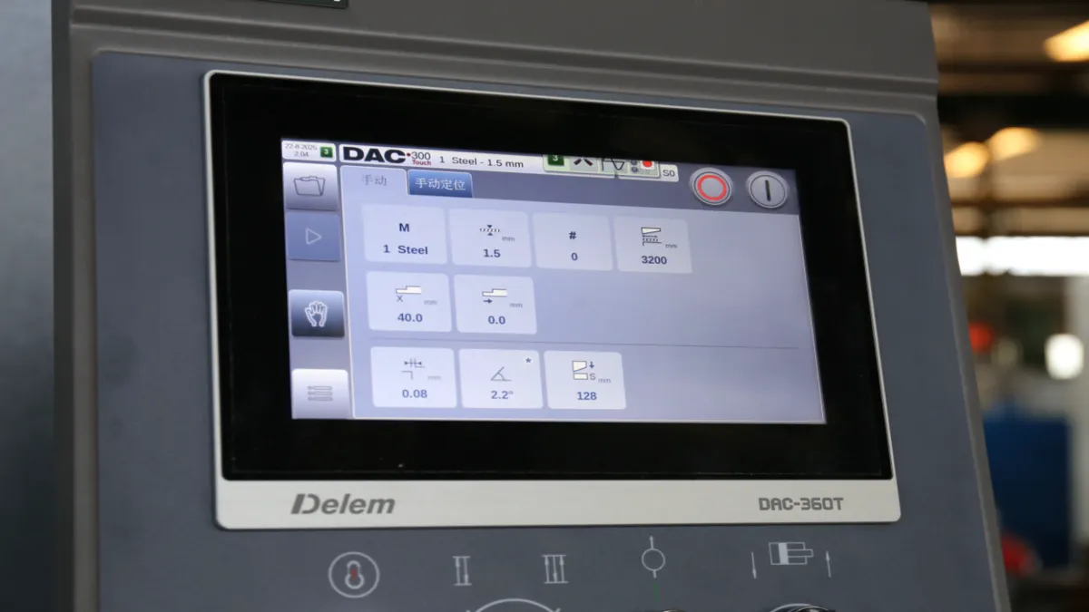
A CNC control system is the brain of any CNC machine. It reads programmed instructions, controls axis movement, manages speed and position, and helps the equipment produce accurate, repeatable parts. In sheet metal fabrication this matters most on the press brake, where the control system governs ram movement, back gauge positioning and bending accuracy.
For a press brake, the level of the control system is not a question of high-end versus low-end, but of whether it can actually produce the parts you need. This guide breaks the types down along three dimensions — motion type, control loop and axis count — and explains what each one means for bending accuracy and productivity in practice.
2. Main components of a CNC control system
A typical CNC control system includes five core parts. Understanding what each one does helps you locate faults faster and lets you ask sharper questions when purchasing.
2.1 Input device
Loads the part program. Common carriers are the control panel, USB and network connections. Where the program comes from and how it is stored directly affects how fast a job change can happen on the shop floor.
2.2 Machine control unit (MCU)
The heart of the system. It reads and decodes the program, generates the axis motion commands and manages auxiliary functions. On a press brake the MCU also handles the calculations tied directly to the bending process, such as angle, crowning and springback compensation.
2.3 Drive system
Consists of servo motors, amplifiers and ball screws, and turns the control signal into physical movement. This layer decides how faithfully a command is executed: motor torque, screw grade and braking response all show up in the finished bend.
2.4 Feedback system
Made up of encoders or linear scales that monitor actual position and speed. This is where closed-loop and open-loop separate: without this layer the system knows only what command it sent, not where the machine actually ended up.
2.5 Display unit
Shows programs, parameters, alarms and machine status. A graphical touchscreen interface, bend simulation and tool libraries all live in this layer. They do not change machine accuracy, but they clearly affect programming and setup time.
3. Types of CNC control systems
CNC control systems are commonly divided along three factors: motion type, control loop and number of axes. The three dimensions are independent — the same machine can be contouring, closed-loop and three-axis at the same time.
3.1 By motion type
These two categories come from milling and cutting practice, but understanding them helps you judge what kind of process a control system was designed around.
- Point-to-point control moves the tool or workpiece from one fixed position to another, with the machining done after the position is reached. Typical uses are drilling, tapping and boring.
- Contouring control governs continuous movement along a programmed path, following curves and complex shapes. Typical uses are milling, turning, routing and laser cutting.
- The specific case of bending: a press brake does not need a tool to travel a whole path, it needs the ram to stop at a precise position and angle. So when judging a press brake control system, the emphasis is not on contouring capability but on axis count, closed-loop feedback and angle compensation.
3.2 By control loop
This dimension sets the ceiling on accuracy and is the one worth pressing hardest on a press brake.
- Open-loop systems send commands to the motors without feedback. They are simpler and cheaper, but cannot automatically correct position errors, so accuracy is lower.
- Closed-loop systems use feedback devices such as encoders or linear scales to monitor movement. If the actual position differs from the programmed position, the controller corrects it automatically, delivering higher accuracy.
- Why closed loop is close to a default on a press brake: bending accuracy depends on precise ram positioning and synchronised left-right cylinder movement. An open-loop system can only believe its command values, so load differences, temperature changes or hydraulic pressure drift produce left-right errors that nothing detects. A closed-loop system corrects them in real time from linear scales, keeping the bend angle consistent across long parts and multi-step bends.
3.3 By number of axes
The axis count describes how many movements are brought under control. The number alone is not a measure of accuracy; it has to be matched against the movements the parts actually need.
- 2-axis: controls X and Y only, for example on lathes.
- 2.5-axis: has three axes but does not move them all at once; the X/Y position is reached first, then Z moves.
- 3-axis: controls X, Y and Z simultaneously, the most common type, used in milling and routing.
- 4-axis: adds one rotary axis, the B axis, for more complex shapes.
- 5-axis: adds two rotary axes, used for undercuts, deep pockets, moulds and aerospace parts.
- Press brake axes use a different set of names: the ram is Y1/Y2, the back gauge uses X, R and Z1/Z2, and crowning compensation is a separate item. The next section sets this out.
4. How CNC control systems work in press brakes
Unlike milling or cutting machines, a press brake CNC control system does not control a cutting-tool path. It controls bending-specific functions: ram movement, back gauge positioning and bending angle.
A press brake CNC controller manages ram position, Y1/Y2 synchronisation, back gauge movement, bend angle, tooling data, bending sequence, crowning compensation and springback correction. It can also store multiple bending programs for quick changeover.
The table below lists the most common controlled items on a press brake and the production problem each one addresses.
One point to note: the two-to-five axis figures in the previous table follow the general CNC classification. Press brakes use a different set of axis names, and real configurations run from two to six axes; multi-axis machines use independent control of X1/X2, R1/R2 and Z1/Z2 to handle tapered and asymmetric parts.
| Axis or function | Function |
|---|---|
| Y1 / Y2 | Left and right ram movement |
| X | Back gauge depth |
| R | Back gauge height |
| Z1 / Z2 | Back gauge finger position |
| Crowning | Deflection compensation |
5. Why closed-loop control matters for press brake accuracy
Bending accuracy rests on two things: the ram stopping exactly where it should, and the left and right cylinders staying in step. On an open-loop system both are merely command values, not measured values.
A closed-loop system returns the ram position from linear scales in real time and corrects any left-right deviation immediately. The result is a bend angle that stays consistent across long parts and multi-step bends, instead of drifting as the workpiece length and the number of operations accumulate. This is also why the repeatability figures of a given machine are noticeably better in a closed-loop configuration than in an open-loop one.
That is also the single most useful question when assessing a control option: is the ram position inferred from the command, or measured from the feedback?
6. How to choose the right CNC control system
When selecting a control system, do not start from a brand name or a specification sheet; start from what the shop actually has to make. Working through the following questions in order will usually narrow the candidates.
6.1 Accuracy requirement
High-precision work needs closed-loop control. This is the first filter, because it decides the control-loop type rather than a single feature toggle.
6.2 Machine type
Press brakes, laser cutters and mills have different control priorities. What a press brake values most is axis synchronisation, angle compensation and a readable bend sequence, not continuous interpolation of a tool path.
6.3 Number of axes
Match the axes to actual needs; more is not always better. Every additional axis brings another servo motor, another feedback set and another element that has to be maintained and calibrated.
6.4 Feedback and compensation
Check for angle compensation, crowning compensation and springback correction. These three are the main sources of bending accuracy and precisely what an open-loop arrangement cannot provide.
6.5 Operator interface
Graphical bend simulation and tool libraries substantially reduce setup time. In an order structure with many part types and frequent changeovers, this often affects delivery more directly than extra accuracy does.
6.6 What to provide when sourcing from GWMT
If you are sourcing a press brake or a press brake control system from GWMT, the following information shortens specification and quotation time considerably: machine model, year and existing controller configuration; the axes you need under control; and the part drawings together with your current programming workflow.
State clearly whether this is a new machine, a control retrofit or a full replacement, because the three need different depths of assessment. A retrofit in particular depends on the condition of the existing feedback system, drives and wiring, because closed-loop capability rests on those components and not merely on a new operator panel.
7. CNC control system comparison table
The table below keeps the parameter dimensions of the source guide, so candidates can be compared on a common basis. The accuracy and cost entries are relative descriptions and do not represent measured values or quotations for any specific model.
| Type | Feedback | Accuracy | Cost | Common use |
|---|---|---|---|---|
| Open-loop | No | Lower | Low | Simple CNC machines |
| Closed-loop | Yes | High | Higher | Press brakes, precision machines |
| Point-to-point | — | Medium | Medium | Drilling, tapping |
| Contouring | — | High | Higher | Milling, laser cutting |
| 2–5 axis | — | Basic → very high | Low → high | Lathes → aerospace parts |
8. Frequently asked questions about CNC control system types
The questions below suit item-by-item confirmation during a machine demonstration or an early specification conversation. They point in the right direction but do not replace model-specific technical data and sample-part verification.
- What are the main types of CNC control systems?
They are classified by motion type, point-to-point and contouring; by control loop, open-loop and closed-loop; and by number of axes, from two to five. The three dimensions are independent, so one machine sits in a combination of all three at once.
- What is the difference between open-loop and closed-loop control?
Open-loop has no feedback and lower accuracy; closed-loop uses feedback to correct errors automatically, giving higher precision. On a press brake that difference shows up directly in left-right ram synchronisation and in the consistency of the bend angle.
- Which CNC control system is more accurate?
Closed-loop systems, because they detect and correct movement errors in real time, which is the root of the accuracy difference.
- What type of control system do press brakes use?
CNC press brakes typically use closed-loop control for ram synchronisation, back gauge positioning and angle correction. The axis count is configured around the parts and can range from two to six.
- How do I choose the right CNC control system?
Base it on machine type, accuracy needs, number of axes, feedback and compensation functions, and operator interface. For a press brake, confirm closed-loop capability and angle compensation first, and only then discuss the interface and programming convenience.
- Is more always better when it comes to axes?
No. The axis count describes how many movements are under control; it does not translate directly into accuracy or productivity. An extra axis only earns its place when the parts genuinely need that movement, otherwise it just adds cost and another maintenance point.
9. Conclusion: the control system sets accuracy, repeatability and efficiency
CNC control systems can be classified by motion type, control loop and number of axes. Open-loop systems are simple and low-cost, while closed-loop systems achieve higher precision through feedback. For sheet metal bending, the CNC control system directly determines press brake accuracy, repeatability and efficiency, and that does not change as equipment is renewed.
If you want to look further into GWMT's press brake CNC control offering — including NC, 2D CNC and 3D graphical control options, offline programming with bend-sequence simulation, and how multi-axis back gauge and crowning compensation are configured — see the press brake CNC control solution page, or contact us directly with your machine situation, the axes you need controlled and your part requirements.
Technical references
Manufacturer references support process explanations; images illustrate selection topics, not an approved GWMT supply specification.