
Contents
- Chapter One: Quality Is Not a Power Problem, It Is a Chain Problem
- Chapter Two: How a Good Cut Is Actually Formed
- Chapter Three: The Nine Variables, One at a Time
- 3.5 Material Properties and Surface Condition
- 3.6 Nozzle Diameter, Concentricity and Standoff Height
- 3.7 Machine Motion, Calibration and Maintenance
- 3.8 Drawing, Programming and Cut-Path Strategy
- 3.9 Environmental Conditions and Thermal Stability
- Chapter Four: Working Back from the Symptom
- Chapter Five: Locking In a Stable Window
- Chapter Six: Applying the Method to a GWMT Machine
- Conclusion: Quality Is a Chain, Not a Power Level
Incomplete cuts, bottom dross, a kerf that is too wide, dross on one side only, burned sharp corners and dimensions that drift — you will have heard all six on the floor today. And almost every time the conclusion is the same one: it needs more power.
The reaction is right most of the time, because it happens to be the easiest thing to do. It is also the easiest way to make the problem worse. More power does melt more material, but it also puts more heat around the cut: a wider kerf, a blued edge, melted corners. You may have fixed the incomplete cut and broken the appearance at the same time.
The real problem is that cut quality is never decided by a single parameter.
1. Chapter One: Quality Is Not a Power Problem, It Is a Chain Problem
Ask ten operators why one batch came out clean and the next one dragged burr, and you will get ten different answers, each one pointing at a single setting. The reality is different. Laser cutting quality is never controlled by one parameter. It is the combined result of how laser energy is generated, focused, absorbed by the material and cleared by the assist gas, together with how precisely the machine follows the programmed path.
That is also why the habit of adding power whenever a cut is difficult costs so much. More power does melt more material, but it also deposits more heat around the kerf: a wider cut, a blued edge, rounded corners and a larger heat affected zone. You may have fixed the incomplete cut and broken the appearance at the same time. This guide exists so that, the next time a cut is not right, you know which variable to touch first.
- Separate three outcomes first, because they are often confused and each one points somewhere different
- Cut quality: burr and dross, edge roughness, striation pattern, oxidation, squareness, heat affected zone
- Cut accuracy: dimensional error, contour deviation, hole roundness, repeatability
- Cut efficiency: cutting speed, piercing time, gas consumption, rework rate
2. Chapter Two: How a Good Cut Is Actually Formed
Every clean cut follows the same physical chain: laser energy, beam focusing, material absorption, melting and vaporization, assist gas ejection, machine motion, programming control, environmental stability.
When a cut fails, the problem sits somewhere along that chain. The nine variables below are essentially that chain taken apart section by section. That is also why working through them in order is far more effective than randomly changing power and speed: the first approach rules out a whole segment each time, the second only gambles on whether you are lucky.
3. Chapter Three: The Nine Variables, One at a Time
The nine variables below are arranged in the order the energy is generated, delivered to the material, reacted with, cleared of slag, executed by the machine and sustained on the floor. The order is not arbitrary: it follows a real physical chain, so working through it in sequence rules out the parts you have already confirmed at each step.
3.1 3.1 Laser Type and Beam Quality
The wavelength, beam mode, spot quality and output stability of the laser decide how well the material absorbs energy and how tight the kerf can be. A stable, high quality beam produces a narrow, uniform kerf. A poor or fluctuating beam shows up as kerf width variation and an edge that differs from one end of the sheet to the other.
One precondition has to be settled first. CO2 and fiber lasers suit completely different materials. CO2, at a 10.6 µm wavelength, is absorbed well by non-metals such as acrylic, wood and plastics, while fiber lasers excel on metals like steel and aluminium thanks to a smaller focused spot and higher metal absorption. Any discussion of reflectivity and absorption therefore has to state which laser type it refers to, which is a common flaw in generic articles.
- What to check: kerf width consistency along the path, edge consistency at different sheet positions, output stability, and whether the laser type matches the target material
3.2 3.2 Laser Power, Cutting Speed and Material Thickness, Matched Together
Power and speed together set the energy delivered per unit length, and they cannot be judged separately. Too little power with too much speed leaves the material short of time to melt and eject, which shows up as incomplete cuts, bottom dross and oblique striations. Too much power with too little speed puts excess heat into the cut, which shows up as a wider kerf, burned edges, melted sharp corners and a larger heat affected zone.
Thicker material generally needs more effective energy, but raising power is not the only lever: speed, focus, gas and nozzle have to be adjusted together. Pulsed processes add frequency and duty cycle on top of that, while continuous cutting should not be presented with them as universal core factors.
The real goal is neither maximum power nor fastest speed. It is finding the stable window between power, speed and thickness, because that window is what lets the same part come out the same on different shifts and under different operators.
3.3 3.3 Focus Position and the Optical System
The focus determines how laser energy is distributed through the thickness of the material. A focus set too high or too low, or one that drifts in the middle of a job, changes kerf width, taper and dross behaviour.
A short focal length gives a smaller spot and higher power density, but a shallow focal depth and a small tolerance, which suits thin material at high speed. A long focal length gives a deeper focal depth and suits thicker work given sufficient power density. Also watch for focus drift from lens heating, and for contamination or misalignment of the mirrors, the protective window and the optical path. When the parameters look right but the quality keeps degrading, inspect the optics instead of pushing more power.
- Symptom signals: kerf width differs between top and bottom, visible taper, quality dropping across one sheet, and needing ever higher power to cut through
3.4 3.4 Assist Gas: Type, Pressure, Flow and Purity
The assist gas ejects molten material, cools the kerf, protects the optics and either drives or suppresses chemical reactions. Oxygen adds heat through an exothermic reaction, which is faster on carbon steel but leaves an oxide layer, and oxygen purity strongly affects the result. Nitrogen gives clean, low oxidation edges, which suits stainless steel, but it demands higher pressure, flow and supply capacity. Compressed air is the cheapest, but its edge quality depends on the material, the thickness and how clean the air is.
Too low a pressure leaves bottom dross; too high a pressure disturbs the melt pool, overcools the kerf or destabilises the edge, so more pressure is not always better. Never analyse the gas by type alone: weigh the pressure, the actual flow, the purity, the condition of the plumbing and valves, the nozzle diameter and the speed as well.
4. 3.5 Material Properties and Surface Condition
Material type, thickness, thermal conductivity, absorption, consistency of composition and flatness all change how the beam interacts with the workpiece. Thicker material needs more power and carries more risk of thermal distortion. Highly reflective metals such as aluminium and copper throw the beam back, which costs energy and makes the cut inconsistent; how that is handled depends on the wavelength and the protection design of the machine, not on a rule of thumb that reflective metal is simply difficult. Highly conductive materials pull heat away quickly, which affects both speed and edge quality.
- Pre-cut material checklist: grade and type, actual thickness and its tolerance, surface cleanliness, flatness, presence of rust, oil, oxide, coating or protective film, and consistency between batches
5. 3.6 Nozzle Diameter, Concentricity and Standoff Height
The nozzle shapes the assist gas into a directed flow into the kerf. Its diameter, roundness, cleanliness, concentricity with the beam and its standoff distance directly govern the flow pattern and how well the slag is cleared. A damaged, clogged or off-centre nozzle skews the gas to one side, which produces dross on one side only, a difference between the left and right edge, a kerf that is offset and of uneven width, local burning and abnormal gas consumption.
The standoff height cannot be set on its own. It changes the effective pressure that reaches the kerf, and it has to be tuned together with the nozzle diameter, the thickness and the gas.
6. 3.7 Machine Motion, Calibration and Maintenance
Even with perfect laser parameters, motion errors cause dimensional and contour deviations. The rails, the rack and pinion, the drives, the servo response, vibration, the condition of the gantry and the height following system all shape the path the beam actually takes. Backlash or weak dynamic response may be invisible on straight cuts but show up on small holes, sharp corners, arcs and fast direction changes.
Maintenance is not only about lifespan, it directly drives consistency. Regularly check the beam to nozzle concentricity, the height sensor, the drive and motion accuracy, the lenses and protective windows, the nozzle and ceramic ring, the cooling system and the gas path with its filters.
7. 3.8 Drawing, Programming and Cut-Path Strategy
Some cuts that look inaccurate are not the machine cutting wrong. They are kerf compensation errors, or a path strategy that concentrates heat. The programming factors include the direction and value of the kerf compensation, the placement of the lead-in and lead-out, the distance from the pierce point to the contour, speed control on small holes and sharp corners, the part cutting sequence and common line cutting, the order of inner and outer contours, heat distribution, and nesting and clamping.
For example, cutting adjacent areas back to back builds up local heat and can warp the sheet, while piercing into a corner causes overshoot, and simply slowing down burns it. This factor is largely missing from many general checklists, yet for accuracy it is often decisive.
8. 3.9 Environmental Conditions and Thermal Stability
Ambient temperature, humidity, dust, power stability and cooling all affect long term consistency. High temperatures burden the chiller, temperature swings shift the thermal state of the machine, high humidity risks condensation on the mirrors and lenses, and dust and fumes contaminate the optics and the moving parts. The environment is rarely the first cause of a single defect, but when quality changes predictably with runtime, weather or shift, check the chiller status, the ambient temperature and humidity, internal condensation, optical contamination, and the stability of the power and gas supply.
9. Chapter Four: Working Back from the Symptom
Do not change everything at once. The reliable way is to work backward from the symptom. The table below is kept from the source and lists the seven most common cutting problems against what to check first and what to check next. Working in that order is far quicker than guessing at parameters, and it does not spoil a process that was already fine.
| Cutting problem | Check first | Check next |
|---|---|---|
| Won't cut through | Power, speed, focus | Gas pressure, lens, material thickness |
| Bottom dross or burr | Speed, focus, gas pressure | Nozzle, gas flow |
| Kerf too wide | Power too high, speed too slow | Focus, standoff height |
| Dross on one side only | Nozzle concentricity | Beam centering, sheet flatness |
| Burned sharp corners | Corner speed, power control | Path and lead-in strategy |
| Dimensional error | Kerf compensation, mechanical accuracy | Thermal distortion, programming path |
| Quality drops over time | Protective window, cooling | Optical contamination, ambient temperature |
10. Chapter Five: Locking In a Stable Window
Change one main variable at a time. Adjusting power, speed, focus and gas simultaneously makes it impossible to know what actually worked, and impossible to hand the result to the next shift.
Run test cuts and record the results. For every material and thickness, log the power, speed, focus, gas pressure and the defect that appeared, and that record is worth more than anyone memory. Once you find a stable window, document it as a parameter library so the same part comes out the same under different operators and different shifts. Also re-verify after maintenance: a changed lens or nozzle can move the focus and the pressure that were correct before.
- Change one main variable at a time
- Run test cuts and record: material, thickness, power, speed, focus, gas pressure, defect
- Build a parameter library so different shifts produce the same result
- Re-verify focus and pressure after maintenance
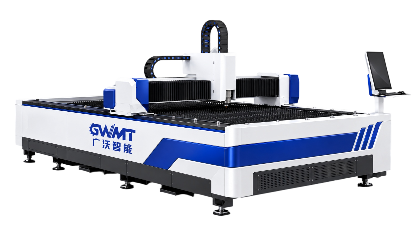
11. Chapter Six: Applying the Method to a GWMT Machine
The five chapters above are general principle. Two things are worth setting out when this comes down to a GWMT machine.
First, the published figures are reference ranges, not a rated capability commitment. The thickness and power relationships in the GWMT material describe the example ranges taken from the supplied technical documents. They help you judge whether a machine is broadly suitable for a given duty. Whether a specific material and thickness cuts through, what the edge looks like and whether it runs repeatably in production are confirmed in a technical proposal written against your actual work. Any reading of a reference range as a promise turns into a problem the first time the batch runs.
Second, buying a machine and running it well are two different things. The same machine produces a different result on a floor where the parameters are logged and test cuts are part of the routine than on one where whoever is free adjusts it. The GWMT guide to operating a laser cutting machine sets out the startup, focus calibration, first article trial cut, production monitoring and routine maintenance as a sequence that can actually be followed. That guide covers running the machine properly; this one covers finding your way back when something goes wrong, and read together they form the whole picture.
- To judge broadly what a machine can cut, the GWMT guide on laser thickness capability separates cutting through from repeatable production
- To match power to the work, the GWMT guide on selecting between 1 kW, 3 kW, 6 kW and 12 kW
- To run the machine properly, the GWMT ten step guide to operating a laser cutting machine
12. Conclusion: Quality Is a Chain, Not a Power Level
Laser cutting quality is not decided by any single setting. It emerges from the interaction of laser energy, focus, material absorption, assist gas, nozzle, machine motion and programming strategy, stabilised by good maintenance and a controlled environment.
The most reliable operators do not chase the highest power or the fastest speed. They understand the whole chain, they diagnose backward from the symptom, and they lock in a stable window through disciplined testing. It sounds ordinary, but not many shops actually do it, and the difference shows up in rework rates and delivery dates.
If you are specifying a laser cutting machine for a new line, or the quality on an existing one keeps drifting, write down three questions and you can start: which nozzle types and focus settings does this machine approve, how often are the optics and the gas path inspected, and are your current parameters recorded in a form the next operator can reuse. Get those three straight and quality stops being a matter of luck and becomes a matter of process.
Technical references
Manufacturer references support process explanations; images illustrate selection topics, not an approved GWMT supply specification.