
Contents
- The Ten Steps at a Glance
- Step 1: Safety and machine readiness
- Step 2: Startup and homing
- Step 3: Prepare the CAD/CAM file and toolpath
- Step 4: Load the material and set the job origin
- Step 5: Calibrate the cutting head and set parameters
- Step 6: Trial cut and first-article inspection
- Step 7: Run the production job and monitor the cut
- Step 8: Troubleshoot common laser cutting problems
- Step 9: Shut down and carry out routine maintenance
- Step 10: Turn it into a repeatable standard procedure
- Frequently Asked Questions
The hard part of running a laser cutting machine is not switching the laser on. It is the startup sequence, focus calibration, parameter setup and first-article inspection — four things that decide whether the machine produces consistent parts or depends on an operator heroics every shift.
The machine can turn one sheet of steel into hundreds of dimensionally identical parts. The trade-off is sensitivity: to hold-down, sheet flatness, gas supply and operating sequence. Get one parameter wrong and what the machine reports is rarely "wrong parameter" — it says "not cutting through" or "dimensions off", while the real cause sits in a completely different stage.
This guide follows the operating sequence as it actually happens on the floor. Every stage is written as a checklist you can follow rather than general principles: what to look at first, which conditions mean you stop, and which adjustments must never be changed at the same time. Read it through and an ordinary production work order becomes a standard procedure any authorised operator can reproduce.
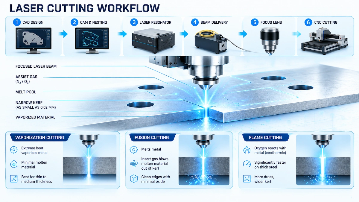
1. The Ten Steps at a Glance
This is a one-way chain. A problem at any stage resurfaces at a later one wearing a different name: file errors surface during setup, setup problems surface in the trial cut, parameter gaps surface in the first article. Every stage you skip plants something further down.
- 1. Safety and machine readiness
- 2. Startup and homing
- 3. Prepare the CAD/CAM file and toolpath
- 4. Load the material and set the job origin
- 5. Calibrate the head and set parameters
- 6. Trial cut and first-article inspection
- 7. Run production and monitor the cut
- 8. Troubleshoot common problems
- 9. Shut down and carry out routine maintenance
- 10. Turn it into a standard procedure
2. Step 1: Safety and machine readiness
Safety and readiness checks must happen before any material is loaded or any program is selected. These are not preliminary formalities: they directly prevent equipment damage, fire events and operator injuries.
- Confirm you are authorised to operate this machine and familiar with the site emergency procedure
- Confirm the material is approved for this machine: grade, composition, thickness and any coating verified against the approved material list
- Confirm the enclosure, guards and door interlocks are in place and functional
- Confirm the extraction system is running, connected and unobstructed; exhaust or filtration must be confirmed operating, since motor noise alone does not prove adequate airflow
- Confirm the cooling system, where fitted, shows the required operating temperature and flow conditions
- Confirm assist gas or compressed air is available at the required supply pressure
- Confirm the emergency stop location before work begins
- Clear and inspect the work area: leftover offcuts, chips and combustible debris on the cutting bed can ignite during the next job, so confirm the correct support structure is installed and free of obstructions
- Inspect operator-accessible components using the method prescribed in your machine manual; if a check reveals contamination, physical damage or an abnormal indication, stop and address it, and never compensate for an equipment fault by adjusting laser parameters
- Any unresolved fault, damaged component or safety-system alarm is a stop-and-escalate condition: interlocks prevent unsafe laser emission and must never be bypassed or defeated under any circumstances
3. Step 2: Startup and homing
Machine startup is a sequenced process, not simply powering everything on at once. The correct order ensures that cooling, gas delivery and the electrical cabinet are fully operational before the laser source initialises.
Before initiating startup, confirm there are no uncleared safety faults or active alarms from the previous session, that all required systems are available and within operating range, and that the cutting area is clear with nobody inside the machine envelope. Then follow the startup sequence in your manufacturer documentation. Sequences differ between laser sources, controller types and auxiliary configurations; what applies to one brand or model may not apply to another. The general principle is that infrastructure comes up before the laser source and control software, but the conditions at each stage are machine-specific.
After startup, complete the homing sequence before loading any material or program. Homing returns all axes to their reference positions, synchronising the controller coordinate system with the machine physical limits. On most fiber laser systems the Z-axis homes first to clear the cutting head from the bed before the X and Y axes move. Confirm all axes complete homing without errors, then check the controller status display for active alarms, axis faults or system warnings.
- If any axis fails to home, an alarm remains active, or the machine does not reach its defined Ready state, do not load material
- Investigate the cause using the fault code and manufacturer documentation, and escalate to qualified service if the fault is outside the operator scope to resolve
4. Step 3: Prepare the CAD/CAM file and toolpath
A correctly prepared file will not compensate for a poor machine setup, but an incorrectly prepared file creates problems regardless of how well everything else is configured. File errors found at this stage take minutes to fix; the same errors found during cutting waste material and machine time.
- Verify the file format is supported by the control software; DXF and DWG are common for fiber laser controllers, but confirm with your specific system
- Confirm document units and overall dimensions are correct: measure a known feature in the software rather than assuming the import preserved the original scale
- Confirm part count and program revision match the production requirement
- Confirm all geometry fits within the usable material area with sufficient clearance
4.1 3.1 Inspect the geometry at high zoom
This is the cheapest step in the whole file preparation, and these are the errors that most often look fine on screen.
- Open contours: a gap in a profile that looks closed on screen but will not separate the part
- Duplicate or overlapping entities, which cause the laser to run the same line twice, adding heat and burn damage
- Stray line fragments or tiny objects, which trigger unexpected laser movements or pierce events
- Annotations or construction geometry assigned to an active cut layer instead of being suppressed
4.2 3.2 Assign layers and apply kerf compensation
Assign operations to layers clearly:
Layer colours help identify groups visually, but the operation and enabled-output status assigned in the controller is what actually runs. A layer hidden in the CAD view is not automatically suppressed in the machine controller, so check each layer output state explicitly. Run a software simulation or toolpath preview and verify the motion matches what you expect before sending the file to the machine.
| Layer | Operation |
|---|---|
| Marks / Engrave | Surface marks, labels, identification |
| Internal cuts | Holes, slots, openings |
| Outer profile | Final part perimeter |
| Special features | Tabs, bridges, partial-cut features |
5. Step 4: Load the material and set the job origin
Confirm the sheet specification first. The actual sheet must match the approved material in grade, measured thickness and surface condition. Nominal thickness from a material label is not always what arrives in production, so measure at multiple points if there is any doubt, particularly for thicker plate or material from a new batch.
- Lay the sheet flat on the correct support structure and confirm it does not rock or bow across unsupported spans
- Use approved hold-downs positioned outside the entire travel path of the head, not just the beam spot but the full moving assembly including the nozzle
- For remnant pieces, check that the remaining material provides adequate support and that existing cut lines do not compromise sheet stiffness under the clamping arrangement
- Set the job origin: depending on the controller it may be a fixed machine coordinate, an edge-found position or a manually set reference point, so confirm which positioning mode is active and that it corresponds to the actual sheet position
- If using edge finding, run it before setting the origin; do not assume the sheet is square to the machine axes
- Run a framing check with laser emission off: the head moves around the outer boundary of the job without cutting, confirming the whole cutting area falls within the usable material and that no part of the travel path risks a clamp or edge collision
- After any change to sheet position or hold-down placement, repeat the frame check before proceeding
6. Step 5: Calibrate the cutting head and set parameters
Focus position determines where the laser beam reaches its minimum diameter. At the correct focal point the beam delivers its highest energy density to the material. Incorrect focus spreads the beam, reduces cutting intensity, increases kerf width and degrades edge quality, and these problems are not reliably solved by more power.
6.1 5.1 Calibrate the focus position and nozzle height
Before calibrating focus, confirm the nozzle type, diameter and installation state match the process requirement. The nozzle opening should be round and undamaged; a dented or partially blocked nozzle disrupts the assist gas flow pattern that removes melt from the cut zone. Check that the nozzle is properly seated and tightened.
Confirm no obstructions or debris are on the sheet surface at the calibration reference point, then calibrate focus using the procedure specified in your machine documentation.
- Autofocus or capacitive height sensing: position the sensor over the required reference area on the sheet surface and initiate the calibration routine, confirming the sensor reads the material surface and not a fixture, an opening or the bed below the sheet
- Manual focus: use the gauge, spacer or focus tool specified for your machine and adjust head height or bed position according to the manufacturer method
- After calibration, confirm the standoff distance between the nozzle face and the material surface matches the process requirement for the material and thickness being cut, and recheck focus whenever sheet thickness, support height or any other factor affecting that distance changes
- Verify focus through a trial cut rather than only by confirming the calibration reading: edge quality, kerf width and cut-through consistency are the practical confirmation
6.2 5.2 How to set laser cutting parameters
With the head calibrated and the sheet positioned, parameter setup follows a defined sequence rather than a from-scratch exercise each time. Start by confirming the material specification: grade, measured thickness, surface condition and any coating or film. Parameters must match the actual material being cut, not just the nominal specification.
Load the starting recipe from the machine parameter library. Most industrial fiber laser controllers include material and thickness specific recipes validated for that machine configuration. Select the recipe matching your material type, thickness, nozzle diameter and assist gas: that is the correct starting point, not a generic values chart from a different machine or system.
The following illustrates how that sequence works on one common material:
- Laser power and mode
- Cutting speed
- Focus position, confirmed against the calibration
- Nozzle type and diameter
- Assist gas type and supply pressure
- Pierce settings: power, duration and pre-pierce mode
- Any material-specific frequency or pulse settings where applicable
7. Step 6: Trial cut and first-article inspection
Every job, including repeat jobs on familiar material, benefits from a trial cut before committing to full production. Nozzle condition changes, material batches vary, and a program revision that has not been noticed can affect the result.
- Use matching material from the same batch and thickness: a test cut on a different grade, alloy or thickness does not validate the production setup
- Where possible use an offcut from the same sheet, positioned on the same support conditions as the production run
- Test with features that represent the actual job rather than a simple square: include the smallest hole in the job, a slot or rectangular opening, a tight external radius, and a sample of any feature that will require assembly or close-tolerance verification
- A square confirms basic cut-through but will not reveal problems on tight corners, small holes or narrow features that behave differently under the same parameters
- Confirm full separation at all edges, including corners and fine features
- Check the burr or dross condition on the bottom face
- Check edge oxidation or discoloration against the expected appearance for this material and gas combination
- Measure part dimensions against the drawing, including hole diameters and slot widths
- Confirm the absence of heat distortion or warping, particularly on thin materials
- If an adjustment is needed, change one variable at a time and retest on fresh material; changing power and speed together makes it impossible to isolate which adjustment produced the result
7.1 6.1 Approve and record the first article
A successful trial cut is only useful if it becomes a documented reference. Without a record, the next operator runs the same job from scratch. Define the acceptance criteria before cutting, not after.
- Dimensions within the tolerance specified on the drawing, determined by the part drawing and the assembly requirements rather than a generic industry standard
- No through-burrs or attached dross requiring rework
- Edge oxidation acceptable for the application
- Hole quality confirmed against any functional requirement such as thread engagement or fastener clearance
- Visual appearance meets the specified standard
- Machine ID and controller version
- Program filename and revision
- Material: grade, supplier or batch reference, measured thickness and surface condition
- Nozzle: type, diameter and installation date
- Focus calibration method and confirmed standoff
- Assist gas: type and supply pressure confirmed at the machine
- All cutting parameters with units
- First-article inspection results with measurements
- Operator name and date
- Keep a labelled sample of the first article with this record where practical: when quality questions arise later, the first-article sample is the direct reference and memory is not
8. Step 7: Run the production job and monitor the cut
With an approved first article and a documented setup, production can begin. Active monitoring continues throughout: a validated setup establishes the starting conditions, not a guarantee for every subsequent part.
- Confirm the loaded material matches the approved specification and the first-article record
- Confirm the correct program revision is selected and targeting the right machine
- Confirm all required layers are enabled and construction geometry and annotations are suppressed
- Confirm the job origin is set and the frame check has been completed for this sheet
- Confirm the parameters match the first-article record exactly
- Confirm extraction and assist gas are running
- Watch cutting behaviour consistency: pierce quality and cut entry should match the first article, and changes in edge appearance or pierce behaviour often precede a more visible quality problem
- Watch smoke and extraction: fume removal should be consistent, and a sudden change in smoke volume indicates something in the process has changed
- Watch part movement: freed parts that tip or shift become collision hazards for the cutting head
- Watch alarms: the first alarm warrants a pause for diagnosis, not an acknowledge-and-continue response
- Never leave the machine unattended during cutting, particularly with thin or combustible materials where a small process change can escalate; remote monitoring through a connected system or camera supplements an on-site operator and does not replace one
- If the job stops unexpectedly, identify the cause before restarting: material movement, head contact, gas supply interruption or program error; restarting without diagnosis risks repeating the root cause immediately
9. Step 8: Troubleshoot common laser cutting problems
Quality defects are diagnostic information, not just reject criteria. Before adjusting any parameter, work through the relevant checks: most cutting problems are caused by setup conditions, not by the laser source itself.
| Problem | Priority checks |
|---|---|
| Laser not cutting through | Material thickness and grade, sheet flatness, focus calibration, nozzle condition, assist gas supply, program parameters versus the first-article record |
| Excessive bottom dross | Assist gas flow and pressure, focus position, cutting speed, nozzle condition and seating |
| Oxidized edge on stainless steel | Nitrogen supply purity and pressure at the machine inlet, gas delivery path, process settings |
| Inconsistent cutting quality across the sheet | Sheet flatness and support, focus calibration, nozzle condition, gas delivery, material batch consistency |
| Incorrect part dimensions | File units and scale, kerf compensation setting, program revision, job origin, material movement during the cut |
9.1 8.1 Incomplete cuts or uncut bridges
An incomplete cut is rarely a signal to increase power. Work through this sequence first:
- Verify material: confirm the actual thickness and grade and that no coating or laminate is present that was not accounted for in the setup, because a different batch at the same nominal thickness can behave differently
- Check sheet flatness: a bowed sheet changes the nozzle-to-material distance across the bed, so the same focus calibration delivers different beam intensity at different positions
- Inspect the nozzle per your machine maintenance procedure: a damaged, offset or partially blocked nozzle disrupts the gas flow pattern that clears melt from the cut zone
- Check the protective lens and optical path using the inspection method specified for your machine: contamination reduces the laser energy reaching the material, so clean or replace only as directed and with approved materials
- Verify assist gas supply at the machine, not just at the supply source: a kinked line, clogged filter or partially closed valve causes gradual degradation that can look like a parameter issue
- Compare the active program settings against the first-article record, verifying power, speed and all relevant parameters including units match exactly
- Only after confirming the setup conditions match the approved test should a parameter adjustment be considered, and then one change at a time within the manufacturer limits
9.2 8.2 Burrs, dross, burn marks or rough edges
Compare any edge-quality defect directly against the accepted first-article sample under consistent lighting conditions before assuming a parameter change is needed.
- Heavy dross on the bottom face often means insufficient assist gas pressure or flow, focus set above the material surface, or a cutting speed too low for the gas type in use
- Oxidized or discoloured edge on stainless steel: check nitrogen supply purity, inlet pressure at the machine and whether the gas delivery path maintains the required conditions, and do not increase power as the first response
- Burn marks at pierce points mean the pierce power, duration or pre-pierce mode may be too aggressive for this material and thickness; also check the lead-in placement
- Consistent striations or a rough edge throughout point to focus position first; also verify the speed and power balance against the approved parameters
- A heat-affected zone wider than expected points to duplicate paths in the file: a second overlapping entity runs the laser over the same edge twice, adding heat without appearing as a parameter change
9.3 8.3 Wrong dimensions, missing features or shifted cuts
Dimensional problems fall into two categories: file or CAM errors, and physical process errors. Identifying which type you are dealing with first saves time.
- If all features are off by the same proportion, check document units, import scale and output scaling in the controller: a millimetre file imported as inches produces a consistent proportional error across all features
- If parts are the correct size but in the wrong location, check the job origin setting and the edge-finding result, and verify the sheet did not move between the framing check and the actual cut
- If features are missing or received the wrong operation, check layer visibility and enabled-output status in the controller: a layer active in the CAD file may be disabled in the machine job setup
- If dimensional errors are small and consistent, measure the kerf and verify whether kerf compensation is applied correctly: if the offset matches the kerf width and compensation was not configured or was applied incorrectly, correcting it and retesting on scrap typically resolves it
- For persistent alignment issues, unresolved sensor faults or suspected optical-path problems, stop and escalate to qualified service: mirror alignment, beam-path adjustment and interlock repair require authorised technical access, and attempting them without authorisation creates safety hazards and can cause further equipment damage
10. Step 9: Shut down and carry out routine maintenance
Shutdown, like startup, follows a sequence. The correct order protects the laser source, maintains cooling system integrity and leaves the machine in a known, safe state for the next operator.
10.1 9.1 Shut down and complete the post-operation checks
Before shutting down, confirm all cutting is complete and the machine has finished its active cycle, allow the required fume-clearance and cooling time before accessing the work area, and remove finished parts and loose material from the bed. Then follow your manufacturer shutdown sequence: the general principle is that the laser source is turned off before the cooling and extraction systems so they can complete their run-on cycles. The exact order and the conditions to confirm at each step are machine-specific, and applying another machine order can shorten laser source and chiller service life or cause faults.
- Confirm the gas supply valves are in the state required by site procedure
- Confirm residual pressure has cleared from the lines as required
- Confirm the work area, bed and cutting head are free of slag, debris and spatter
- Complete any required post-operation records
10.2 9.2 Perform routine maintenance after operation
Maintenance falls into three distinct categories. The specific tasks and intervals for each depend on your machine model, operating environment and manufacturer requirements, so use your maintenance schedule as the authoritative source.
A note on lens cleaning: using the correct optical tissue, approved solvent and the prescribed method prevents gradual energy loss from contamination buildup. Cleaning with the wrong materials — household glass cleaner, paper towels or compressed shop air — can scratch or contaminate the optic and cause more damage than the contamination it was meant to remove. If the lens shows damage or internal contamination beyond operator-level cleaning, report it for service assessment.
| Category | What to address |
|---|---|
| After each job | Remove offcuts, slag and debris from the cutting bed, scrap tray and surrounding area, and check for and record any alarms, quality deviations or process anomalies from the run |
| Routine inspection | Check nozzle condition and record replacement if worn, inspect the protective lens and clean it only as directed with manufacturer-approved materials, verify gas path filters and connections, and confirm extraction system operation |
| Scheduled maintenance | Cooling system fluid condition and level, lubrication of linear guides and motion components, dust extraction filter replacement, and drive and transmission inspection, all per manufacturer-defined intervals |
11. Step 10: Turn it into a repeatable standard procedure
Operating a laser cutting machine reliably comes down to a consistent sequence: verify safety and machine readiness, start up and home, prepare the file, load and position material, calibrate focus and set parameters, trial cut and approve the first article, run and monitor, shut down and record.
Every stage connects to the next. File errors surface at the setup stage, setup conditions show up in the trial cut, and parameter gaps become visible in the first article. Skipping any stage means borrowing problems that appear later and are harder to trace back to their source.
For production environments this workflow should be formalised as a written standard procedure rather than a mental checklist. A written procedure ensures any authorised operator can reproduce an approved setup, keeps quality records consistent, and means troubleshooting starts from a known baseline. The job record created at first-article approval is the foundation of that system.
If you are specifying fiber laser cutting machines for a new production line, or looking to improve process consistency on existing equipment, the most productive conversation to have with any supplier is about your specific material range, thickness requirements, part geometry, tolerance expectations and production volume. A machine configured and supported for your process will outperform a more powerful machine without that context. Put plainly: a well-run laser cutting operation is not defined by the machine wattage, it is defined by how consistently the process is set up, validated, monitored and documented.
12. Frequently Asked Questions
The six questions below suit item-by-item confirmation with a customer, a colleague or a supplier.
- What should you check before operating a laser cutting machine?
Before loading any material, confirm the enclosure and interlocks are functional, extraction is running and unobstructed, cooling and assist gas are at the required operating conditions, and the work area is clear of debris. Check the nozzle and optical path condition using the inspection method specified for your machine. Any unresolved fault or safety-system alarm must be resolved before proceeding, and a protective interlock must never be bypassed.
- How do you start a fiber laser cutting machine?
Follow the startup sequence in your manufacturer documentation: startup procedures differ between laser sources, controller types and auxiliary configurations. The general principle is that support systems — cooling, extraction, gas supply — come up before the laser source initialises. After startup, complete the homing sequence to synchronise all axis positions, then confirm the machine reaches its Ready state with no active alarms before loading material or a program.
- How do you set the parameters for laser cutting?
Start by loading the material-specific recipe from the machine parameter library rather than entering values manually from a generic chart. Confirm the recipe matches your material grade, thickness, nozzle size and assist gas type. Check that all speed and power units match the controller format before entering values, then perform a trial cut on matching scrap and inspect dimensions, edge quality and cut-through before approving the setup for production.
- Why is a trial cut necessary before production?
A trial cut validates that the physical setup — material batch, focus calibration, nozzle condition, gas supply and parameters — produces parts that meet the required dimensions and edge quality under current conditions. Material batches vary, consumable condition changes and program revisions can go unnoticed. First-article approval confirms that the actual output meets the acceptance criteria before committing the full production sheet.
- What causes poor edge quality or incomplete cuts in laser cutting?
The most common causes are incorrect focus position, insufficient assist gas flow or pressure, a worn or misaligned nozzle, a contaminated protective lens, and parameter settings that do not match the actual material and thickness. For stainless steel an oxidised edge usually points to nitrogen supply purity or pressure rather than laser power. Before adjusting any parameter, verify the physical setup — focus, nozzle, gas delivery — against the approved first-article conditions.
- When should an operator stop the machine and request technical support?
Stop and escalate for any unresolved interlock fault, persistent alarms that do not clear after a correct restart attempt, suspected optical-path or lens-alignment problems, head collisions or unexpected mechanical behaviour, and any situation where cutting quality cannot be restored through verified operator-level setup checks. Beam alignment, mirror adjustment and interlock repair require qualified service access, and attempting them without authorisation creates safety hazards and the risk of further equipment damage.
Technical references
Manufacturer references support process explanations; images illustrate selection topics, not an approved GWMT supply specification.