Frame and bed
Frame rigidity, bed envelope, access, and foundation planning are reviewed with the die and production duty.
A rigid-frame pneumatic press platform for repeat punching, blanking, forming, and compatible progressive-die production.
RESUMEN DEL PRODUCTO
JH21 selection begins with the die, force curve, stroke, shut height, feeding method, guarding, and intended production duty. The whole press scope must be reviewed with the real tool and part.
ESTRUCTURA DE MÁQUINA
Frame rigidity, bed envelope, access, and foundation planning are reviewed with the die and production duty.
Slide travel, guide condition, and adjustment range are matched to the shut height, die envelope, and work sequence.
The drive, clutch/brake scope, and control method are selected with stroke pattern, cycle demand, and site operating procedure.
Die dimensions, fastening, material direction, worktable access, and repeat stops determine the useful press configuration.
Manual or matched feeding, discharge, part handling, and inspection flow should be reviewed with the output target.
Guarding, control mode, access, service space, and safety procedure are confirmed before operation.
PUNTOS DE CONFIGURACIÓN
Provide die drawing, blank or strip direction, stages, shut height, required force calculation, and expected work position.
Confirm material grade, thickness, coil or blank format, finished geometry, edge condition, and tolerances.
Define feed method, target output, loading, discharge, inspection, guarding, and operator method.
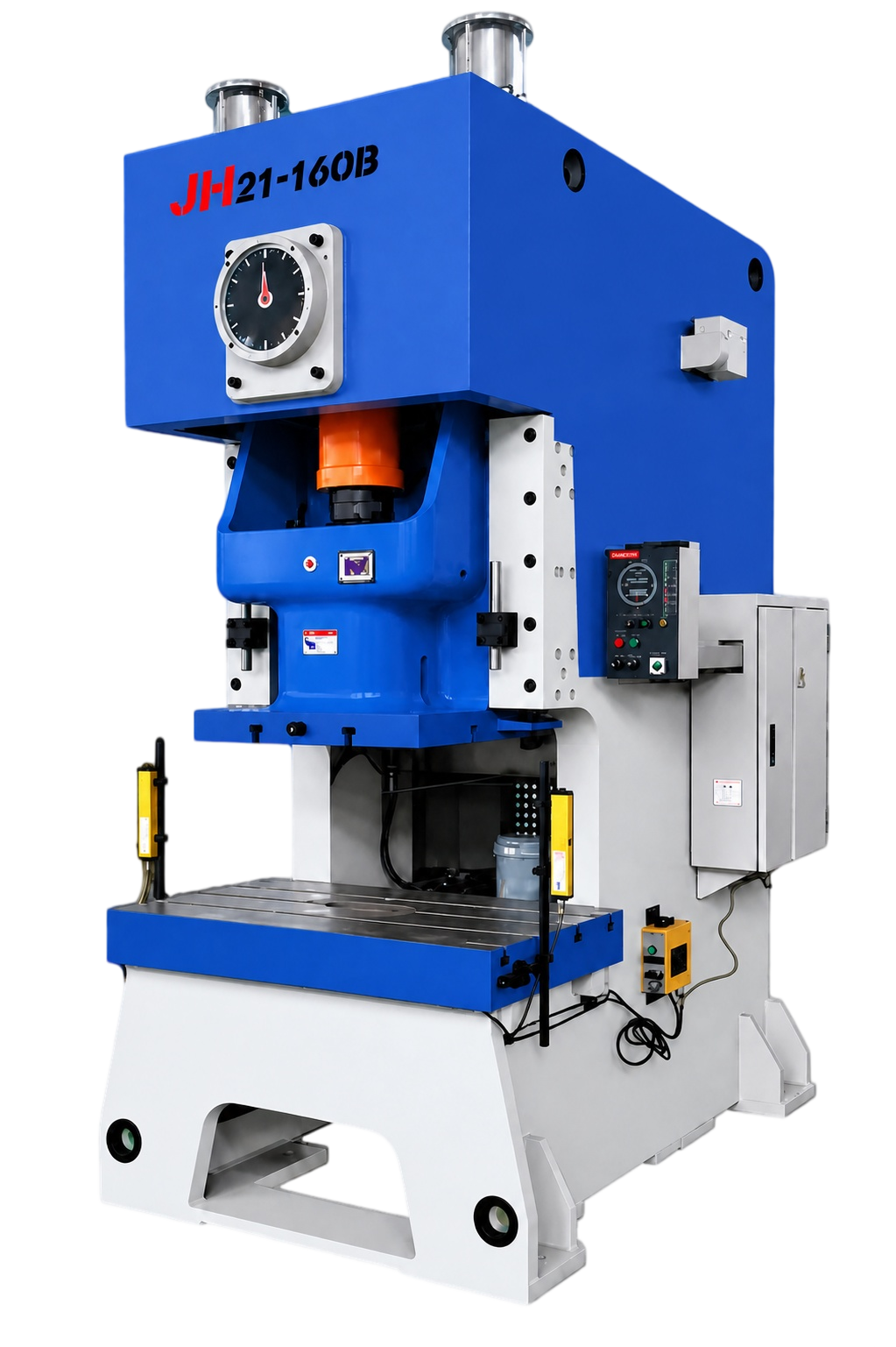
La imagen es solo referencia estructural de JH21-160B y no establece equivalencia con JH21-160. Los golpes fijos y variables son valores separados; utillaje y configuración final se confirman en el acuerdo técnico.
| Parámetro técnico | Código | Unidad | JH21-25 | JH21-45 | JH21-60 | JH21-80 | JH21-125 | JH21-160 | JH21-200 | JH21-250 | JH21-315 | JH21-400 |
|---|---|---|---|---|---|---|---|---|---|---|---|---|
| Nominal capacity | Pe | kN | 250 | 450 | 600 | 800 | 1250 | 1600 | 2000 | 2500 | 3150 | 4000 |
| Nominal force travel | Sp | mm | 3 | 4 | 4 | 5 | 6 | 6 | 6 | 6 | 7 | 8 |
| Slide stroke | S | mm | 80 | 120 | 140 | 160 | 180 | 200 | 250 | 250 | 250 | 270 |
| Fixed slide strokes per minute | n | times/min | 100 | 80 | 70 | 60 | 50 | 45 | 45 | 30 | 30 | 30 |
| Variable slide strokes per minute | n | times/min | 60–100 | 50–80 | 45–70 | 40–60 | 35–50 | 30–45 | 25–45 | 20–30 | 20–30 | 20–30 |
| Maximum die set height | H2 | mm | 250 | 270 | 300 | 320 | 350 | 400 | 450 | 500 | 500 | 550 |
| Die height adjustment | t | mm | 50 | 60 | 70 | 80 | 90 | 100 | 110 | 120 | 120 | 120 |
| Throat depth | C1 | mm | 210 | 225 | 270 | 310 | 350 | 400 | 430 | 450 | 450 | 490 |
| Distance between uprights | d1 | mm | 450 | 515 | 560 | 610 | 670 | 736 | 910 | 980 | 980 | 1050 |
| Slide bottom size L–R | a | mm | 360 | 410 | 480 | 540 | 620 | 700 | 880 | 950 | 950 | 1020 |
| Slide bottom size F–B | b | mm | 250 | 340 | 400 | 460 | 520 | 580 | 650 | 700 | 700 | 750 |
| Die shank diameter | d | mm | 40 | 50 | 50 | 50 | 70 | 70 | 70 | 70 | 70 | 70 |
| Die shank depth | l | mm | 65 | 60 | 70 | 65 | 90 | 100 | 100 | 130 | 130 | 130 |
| Bolster size L–R | C | mm | 720 | 825 | 930 | 950 | 1100 | 1170 | 1390 | 1500 | 1540 | 1700 |
| Bolster size F–B | D | mm | 400 | 440 | 520 | 600 | 680 | 760 | 840 | 880 | 880 | 950 |
| Falling-hole diameter | φ | mm | 150 | 150 | 150 | 150 | 160 | 180 | 200 | 200 | 200 | 200 |
| Bolster thickness | H3 | mm | 80 | 110 | 130 | 140 | 155 | 165 | 180 | 190 | 190 | 210 |
| Bolster surface height | H1 | mm | 780 | 800 | 900 | 900 | 900 | 900 | 1000 | 1000 | 1000 | 1100 |
| Overall dimensions L–R | A | mm | 1496 | 1585 | 1540 | 1765 | 2040 | 2305 | 2600 | 2660 | 2720 | 2850 |
| Overall dimensions F–B | B | mm | 945 | 1075 | 1200 | 1200 | 1320 | 1420 | 1540 | 1640 | 1680 | 1750 |
| Overall dimensions H | H | mm | 2120 | 2391 | 2570 | 2725 | 3035 | 3215 | 3800 | 3865 | 3865 | 4150 |
| Foundation distance F–B | a | mm | 980 | 1075 | 1100 | 1210 | 1430 | 1665 | 2020 | 2100 | 2140 | 2260 |
| Foundation distance L–R | b | mm | 660 | 760 | 840 | 920 | 1040 | 1140 | 1840 | 1740 | 1810 | 1750 |
| Motor model | — | — | Y100L–4 | Y132S–4 | Y132S–4 | Y132M–4 | Y160M–4 | Y160L–4 | Y180M–4 | Y200L–6 | Y225M–6 | Y250M–6 |
| Motor power | — | kW | 3 | 5.5 | 5.5 | 7.5 | 11 | 15 | 18.5 | 22 | 30 | 37 |
| Approximate weight | — | kg | 2450 | 3550 | 5150 | 6450 | 9550 | 13600 | 19200 | 23200 | 26600 | 31600 |
TAILORED TÉCNICO PROPUESTA
Share planos, materiales, producción objetivo, y proceso actual constraints. An engineer can usar them a preparar the siguiente conversation.
GRUPO TEMÁTICO · Cizallado, curvado de chapa y punzonado
Selección de cuchillas, principios del curvado de cuatro rodillos y aplicaciones de la prensa eléctrica de prueba.
Estas guías explican el proceso y los criterios de selección. La configuración final se confirma en la propuesta técnica.
Comparta el plano, el grado del material, el rango de espesor y la producción objetivo. GWMT revisará la configuración para su aplicación.